After working a lot in section 42C today, I understand why a lot of people had trouble with the Avionics installation. It's pretty much just plug-and-play if Van's hadn't made it unnecessarily complicated and confusing. I found so many errors and bad step ordering and also left out instructions, that I will try to write this all down now, so the next builder won't have to figure this out until Van's (hopefully) revises the section.
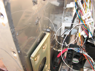
The first laugh this morning was caused by an interfering rivet when installing the transponder mount bracket.
This rivet holds the nutplate for the manifold pressure computer that will get mounted under the antenna shelf. I don't think this device disappeared in the Skyview installation, at least there's no information about it. So I assume this nutplate is necessary. On the page where it shows the installation of the mount bracket, it shows only the cutout for a nutplate but not an installed one. The interference is minimal and the transponder installs in the mount bracket without trouble, so I left the rivet untouched. One could probably grind it down a bit (1/16") and remove the problem.
So I hooked up the cables to the transponder.
Then I worked on the ELT antenna shelf installation. Nowhere does it take into account, that I had to drill out rivets that I was supposed to install in previous instructions. When they asked to final-drill the nutplate holes with #19 bit I just used that to drill out the rivet as well.
I followed the plans by screwing a screw into the nutplate from the wrong end, using the protruding part of the screw as a centering tool. With the left hand I held the nutplate with screw in position while drilling with the other hand into the bar, using the eyelet as a drill template. After the first hole I clecoed it and drill the second hole. Rinsed and repeated twice it gave me this:
Then the next joke showed up the plans - or actually, it was lack of instructions that made me chuckle. The next step asked to rivet the nutplates in. Well, with no word was mentioned that these rivet holes should get countersunk for a CCR-264 flush pop-rivet. So, I deviated from the plans again, and did that anyway.
Deburring these rivet holes was another story. The lightening holes on the opposite side of the bar were not all in the right location to give me good access to the holes, so I had to resort to the edge deburring tool and work from the drill side to get the job done.
After a while I had the nutplates all in.
I held off on the actual installation of the antenna shelf until after installing the ELT itself. Which was my next task.
Having the fuse on the left side creates a bit of an awkward position to work on that because it's over head but still better than having it on the belly.
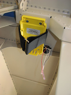
The following first step in the ELT installation should actually be the second step. What you should do first is what Van's has you do last, which is simply stupid. The last step is to final-drill the lower aft mounting hole with a #19 bit. They even ask you to deburr, but they don't reveal how you're supposed to do that on the drill side when you have already riveted the bracket in place. So, please, go to 42C-15 and mark step 10 to be done BEFORE step 6, and step 9 before step 8. You'll see why when you do it.
Bracket was clecoed in place and the two of three holes for the rivets where match-drilled. It's impossible to deburr the holes other than from the drill side.
My fingers are not even long enough to just feel for the burr on the upper hole.
It was time to rivet the three wide head rivets on. I noticed that they are quite short and I believe they are actually not long enough to correctly attach the bracket to the structure. You can feel after pulling them that the shank is not really protruding very far on the other side, nor is there a lot of a wart buildup that would secure it.
Nothing exciting happened manufacturing the cables for the ELT buzzer. It was so unexciting that I totally forgot to take a picture. Sorry! I installed the wire at the 4th mounting point of the bracket and put the ELT under its velcro strap. Then I came across a weird request to put two gel strip over the male pins of the ELT connector. I researched this a bit and found out that this is supposed to make the connection water proof. Oh well, I don't think it makes any sense that the connector is water proved when the aircraft is submerged in water, or the antenna for that regard. I did it anyway.
And I also mounted the antenna shelf including antenna.
And finally, I attached the cables and made them look pretty.
I went back to the ADAHRS installation as all nuts and screws had arrived earlier this week. I decided to mount the ADAHRS unit to the brackets outside of the tailcone. I used brass nuts and screws separated from the aluminum with nylon washers under the nut and the screw head. Blue Loctite should keep the nuts in place. I did torque seal them though, so I can see if they would get loose.
It is super easy to hook-up the wires before even clecoing the unit in. However, Van's again has forgotten to mention an important detail in this step. You will later find out, if you read very carefully, that the backshell on the 9pin D-Sub connector should get exchanged against an ES 9 PIN BACKSHELL 2 and that the backshells with thick thumbscrews would cause trouble with the magnetometer. Well, took a look at this backshell they want you to install. Other than smaller screws instead of the massive thumbscrews this different backshell needs just as many magnetic parts than the one that is on the harness already. I tried it. All the screws and utilities are magnetic and the 9pin D-Sub connector itself is magnetic. I decided to just remove the thumbscrews from the existing backshell and leave it in place without securing it to the ADAHRS unit. It does not feel like the plug could work itself out.
With the bracket cleoed in place, I was now able to shorten the pitot and AOA lines to the correct length and hook them up to unit. This is where another funny incident occurred. 42C-19 step 2 asks to install these nylon pitot line connectors and to refer to section 5Y for details about this. Well, there is no section 5Y. There is 5X and then it's over. So I am not sure if I installed these nylon plugs correctly. I just tightened the front part that goes into the ADAHRS with my hand and then added an 1/8 of a turn with a wrench. Then I tightened the nut that secures the hose in the connector. The pressure test will show if that was sufficient. For the AOA plug I used a bit Teflon tape around the threading and a wrench to force it in. I think that will be air tight.
Update: I received a comment on VAF this morning saying "Section 5Y in updated Sections 1-5 dated 11-12-2011, page 5-15, Fig 2.". I thought I had looked at the latest revision of the instructions when I looked for 5Y but obviously didn't. I checked again this morning, and indeed, there is a 5Y section and it pretty much told me to do what I've already done anyway. Thanks, Jim!
And then it was time clean up the hoses and cables and the cable-ties.
And also time to rivet the bracket back in place - for the third time.
I was getting tired at that point but I also thought that installing the GPS antenna couldn't really take that much time. You know where that's going, right?
So, I had heard that a few people had a problem matching the holes of the extension plate to the GPS mounting holes. I agree that you have to try a bit as there is one - and only one - position in which it will work, but mine matched just fine.
What didn't fit was the screws to hold the extension plate to the antenna shelf though. On 42C-17 step 4 they tell you to use the hardware from figure 2 to mount the GPS to the shelf. Well, that won't work as they ask for two stainless screws of the type AN528C 632 R8. Notice the 632 which indicates a #6 screw. After noticing that the screw wouldn't fit I checked with the instructions somewhere in the 2X section where it had to rivet those nutplates to the shelf and they clearly asked for K1000-08 which are plates for #8 screws. After a bit of hunting around I assumed that the screw they should ask for is AN526C 832 R8. This is the same type, only in #8 size. I have plenty in my sorter, so I used those and they fit not just in the nutplate but also perfectly through the extension plate. The latter tells me that the plans are likely wrong here.
You notice this nice silvery and shiny GPS harness backshell? They asked you to install a ES 9 PIN BACKSHELL around the plug. After chasing though the inventory lists I couldn't find where it was supposed to be. I expected to see a backshell with a snap on lock like the others, and also one that's black. However, it turned out that the silver one that came in the box with the GPS antenna must be the one they mean as it also had a "GPS" label already put on it.
Enough fun for one day. The next thing will be more panel work as my panel cutter arrived today.
Thursday, May 10, 2012
Subscribe to:
Post Comments (Atom)


No comments:
Post a Comment