Showing posts with label Lighting Kit. Show all posts

Monday, July 30, 2012

Lighting Installation Completed

The last part of the mechanical lighting installation was to add an air scoop to the Ducati voltage regulator. There is more to this section but this does not affect any installation of sorts but only modification to the weight and balance and additional paperwork for the registration and certification.

After deburring the parts, I did a trial fit on the installed regulator.

Then I marked the opening on the fiberglass baffle where the hose would connect to later.

This hole is pretty inaccessible, so I used a #12 pilot drill bit and opened it up with the Dremel before I used the step drill bit to come up with a clean hole. The step drill bit was turned by hand and a wrench, which took a while but worked ok.
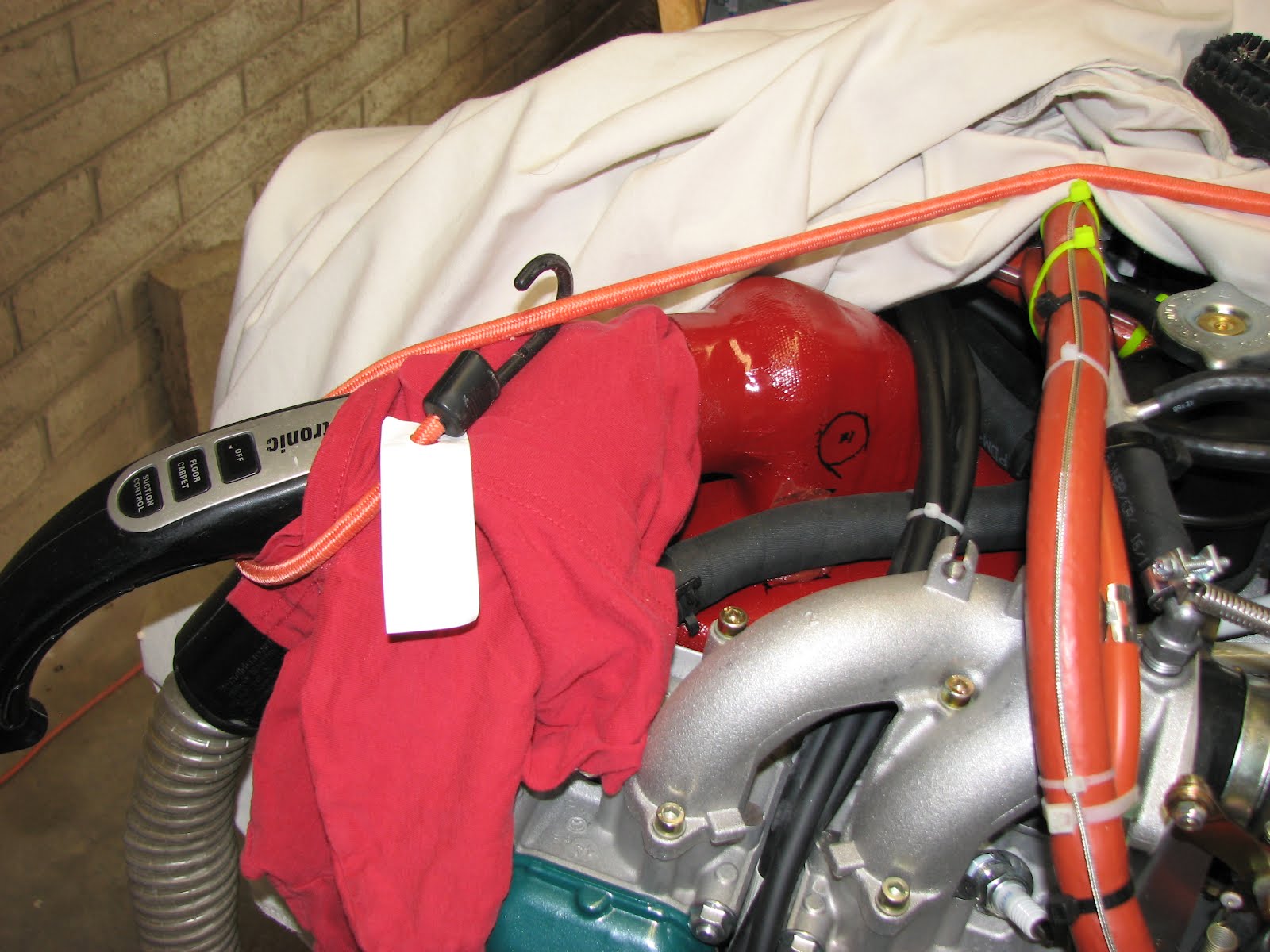
I also came up with a spiffy way of keeping debris out of the baffled area. This is my way of a vacuum hook up t the baffle.

The 3/4" is the perfect size for the hose.

I removed the regulator and got ready to match drill the cooling fins with the air scoop cover.

A clamp kept the cover in place during match-drilling.

I filled the corners of the cover from the inside with RTV and used blue tape to ensure it wouldn't squeeze out.

Then I riveted the cover on. I also applied a thin coat of thermal compound along the
fins where they touch the cover to better the heat transfer and enlarge the cooling surface. The regulator is known to overheat and the Tucson heat won't help that either.

Before installing the regulator on the firewall shelf, I applied RTV to the hose/surface connections and let it settle. Otherwise the hose would pull itself out of the regulator cover when applying a slight pull to the hose.

The next day the RTV had settled and was holding the hose in place so I could finish the installation and tie-wrap the hose in place.

Again, I applied some thermal compound to the flanges that connect the regulator mechanically to the shelf. It's not much surface contact but it might help to get the heat away. What I do not understand in this layout is that the water radiator is routing warm air towards the regulator in this setup. I believe a deflector shield in front of it could help to avoid this.

This was the last step in Section 40 until the paperwork has to be done.

Sunday, December 19, 2010

And then there were two!

As of today I am a member in the Pro-Seal club. That stuff really is messy! Sticks to everything that can't run fast enough and then spreads around with everything you touch. You really want to prepare the area well before applying this mess.
I started around noon and thoroughly prepared the two separated work areas as I wanted to put the Pro-Seal on both nav light fairings so not to waste the mixed up compound. Taping the wing tip skin was easier than I thought as the electric tape really stretched well when persuaded. Cutting the thinner tape was hopeless though. I tried to match the idea as well as possible I think it came out well.


On the right wing I didn't put enough of the Pro-Seal onto the fairing and it did not squeeze all the way out, so I had to fill that from the outside. I think after painting you won't even notice this anymore.


The left wing came out better in that respect. By the way, before sealing this area I made sure that the nav light wiring was working by hooking up the light and driving it with a battery again. Just as I had done the day before on the right wing.


While the Pro-Seal was curing I took the time to put the bandsaw to more work for Section 18 and cut the angle and the AEX tie downs to rough size.


Then my wife helped me to carry the wing from the work area to the cradle. I sealed the holes with paper and tape again and tied the wings to the cradle to withstand any kind of gusty or stormy day.

And then there were two!

Saturday, December 18, 2010

Right Wingtip Finished

In anticipation of sanding and cutting fiberglass today and in the near future (Finish Kit), I decided to give in and get a bandsaw as well as a belt sander. This triggered quite an odyssey as my favorite store, Harbor Freight didn't have a band saw I would have liked. I got the belt and disc sander there though and then went to Home Depot to look for a Ryobi bandsaw, the one I've seen Dave in Ohio using. That was successful as far as it concerned the saw but they were out of fine bandsaw blades (!^%$@#) so on my way home I passed Lowe's and picked up a Bosch 18TPI saw blade. I also finally bought an electric screwdriver to drive recently purchased hex deburring bit. It is kind of silly to manually deburr the tailcone and both wings and then get the motor driven version when there's not that much left but I have a feeling I might become a repeat offender and then I'll have it in the shop.


I put both machines right to work after finishing the wingtip skin. I still had to match drill and deburr the 6 holes on the trailing edge of the little triangular skin closeout. And, yes, I put the deburring driver to work as well. It's really nice on my wrist!. Forgot to take a photo of the tool though.


Finally done with Section 17, the right wing is done! Exactly 90 hours spent on Section 17, this sums up to 176.5 hours to finish both wings - short of the flaperons. Current Hobbs meter on the build shows around 370 hours.

I used the bandsaw to cut close to the scribe line of the nav light fairing. NICE! The fine blade went through it like a hot knife through butter and I could very easily and precisely control the cut. I love this saw! Then I used the belt sander as much as possible to sand to the scribe line and the rest was done by hand. The inner cut could get done by anything else but the angle grinder again as there just wasn't enough clearance for anything else. But that was done within a few minutes and I just ignored the dust or stood windward of the little wind we had. The fairing was quickly sanded to shape and I could drill the rivet holes and prepare the epoxy to fill the wingtip rib side.


I was a little better this time about the amount if epoxy I put in there but still I had to grind a little bit out to allow for the upper nut to have enough room. I also trimmed back some excess epoxy that had been squished towards the inside of the fairing where it wouldn't have any structural function anyway. I cleaned off the car wax I had used on the wing, crimped the Molex connectors on the wires, hooked up the light with a battery and tested all the wiring in the right wing by firing those lights of.
Great show as it was dusk already!
Then I clecoed the fairing back on to be ready to run the masking tape around the outline of it tomorrow and join the Pro-Seal club.

Thursday, December 16, 2010

Landing Light Finished

So the double sided tape arrived and I could finally install the glass cover tonight after work. The screws and the glass nicely shaped the skins back and it looks real nice. I cleaned the glass before putting it in and so you have to look real hard to notice that it's actually really in there :-)

Monday, December 13, 2010

Landing Light Almost Finished

This is how the day started. With a plexiglass cover that obviously is not shaped for our -12. The bag had a handwriting on it saying "-10, -12", so I assume all that extra plastic is for the -10.


To get a rough cut done and a better idea of the final shape and to allow an insertion into the cutout I taped the cover onto the outside of the cutout, the long side of it on the belly of the wing seem to fit better to the wing foil, and then marking a line ( free hand) just short of the first rivets holding the landing light ribs behind the leading edge.
Then I clamped the cover in the vise and used a Dremel cutting disc to cut (melt) the excess plastic off. You reLly want to wear a face mask when doing this as pieces of hot plastic a flying all over and also in your face. Ask me how I know.


I put the reduced size cover back on the cutout, aligned it to best fit with the air foil and taped it in place. Then I drew a line through the center of the two inner screw holes onto the cover and also added an outer line just 1/4" outside of this inner screw line. This outer line would be the trim line to cut the cover to. I did the same on the bottom.


Back to cutting and back to the cutout. A first trial fit looked promising, after setting the landing light back to its rearmost position, I could just clear the light ribs to get the cover in. This tight clearance actually helped in the next step where you're supposed to put tape around the cover to help pulling it into shape while drilling the screw holes. This is a 3 hand job as you should pull evenly when doing this and this would require two hands for pulling - leaving no hand for drilling, so you need a helper. OR, your cut is so tight that the light has no real choice but to stay in place which was the case with my cut. I followed the manual anyway, just in case I could pull it out another 1/64" with one hand.


I started drilling the upper side (which is actually the belly of the wing as it lies upside down), pulling on the tape closest to the hole I drilling and starting in the corners. The reason why I started in the corners is that the skin has the least tendency to bulge there. I clecoed every hole right after drilling, fixating the cover. The inner holes where the skin was trying to bulge away from the cover, I could press the skin down with my free hand (I didn't pull on the tape there as the clecos held it in place) while drilling.


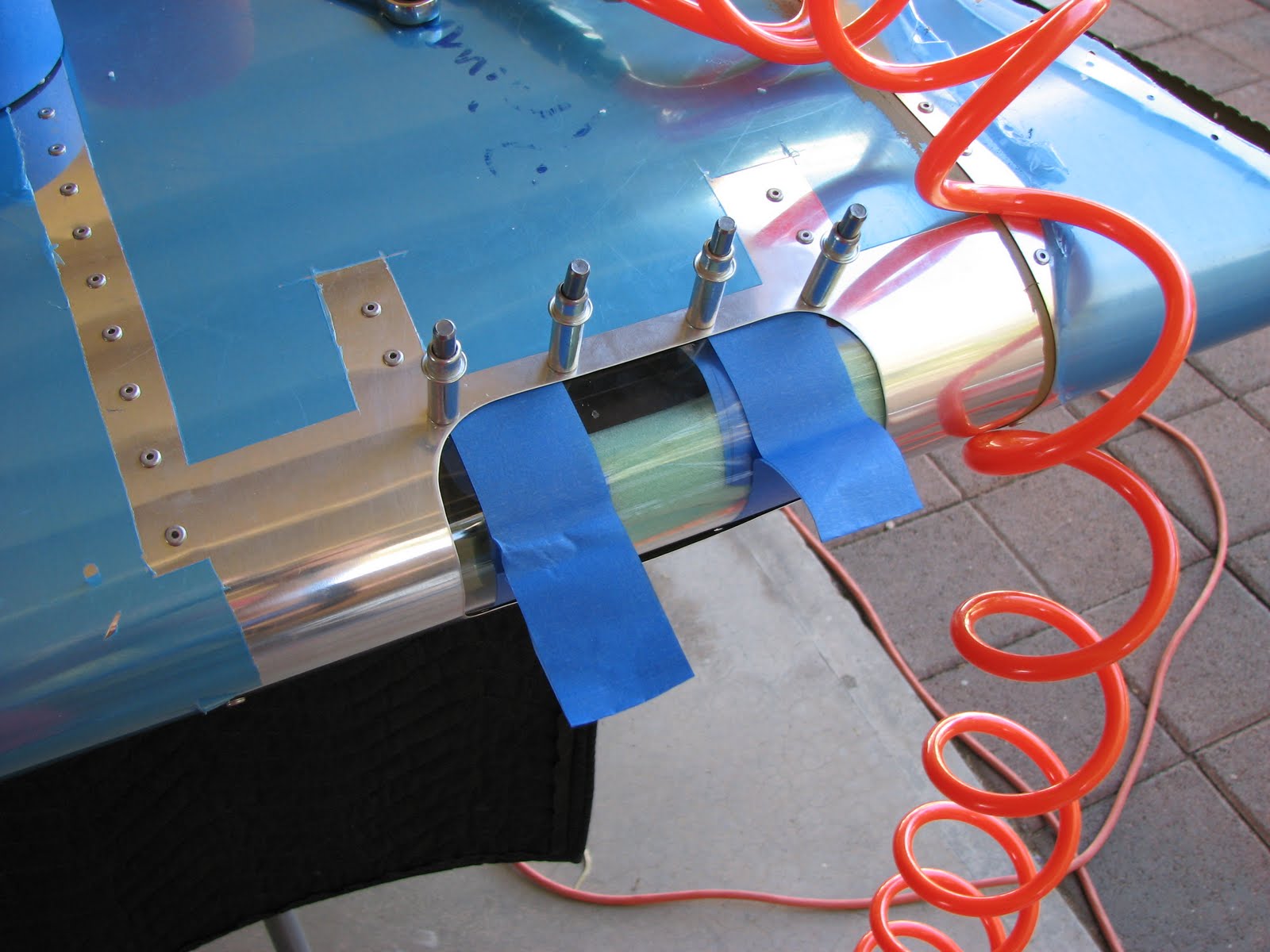
For drilling the lower screw holes I used the same approach although I found it hard to pull while drilling because I would have had to swap my hands, using the weak hand for drilling. I found some foam to stash in between the landing light and the cover to provide some pressure from the inside. Obviously I did this through the open wingtip. The foam held it tightly in place. Then I marked the left and right side of the cutout on the cover for the next trimming process.


By the way, there was no #30 plexiglass drill bit in my Avery tool kit. They provided a #40 and a #27. The latter is required to final drill the holes in the cover. The manual was asking to start drill #30 through the screw holes, probably to match the size of the hole which could help center the drill IF it wasn't a plexiglass drill. A plexiglass drill has a long, sharp tip and so it wouldn't get guidance from the surrounding hole early enough to make a difference I believe. I used the #40 drill to start the holes, taking extra care to center it well. This is how it came out.


Then I used the nutplate brackets to put the final markings on the glass and got started on the final trimming step.


After a lot of cutting and melting (the shop looks like a mess!) and sanding (I wish I had a belt or disc sander!) this is how it came out.


Now it was time to countersink the plexi to match the dimples in the skin that I put in in the same step. The already installed landing light looked like it could interfere with this task but allowed for just enough clearance to get the yoke in there when moved to its rearmost position and using the full travel of the angular axis (full up and down travel).
For countersinking I used the hand tool. It turned out that the deburring bit has the same thread as the countersink bit and so I put it in the crank handle and used a screw head as reference.


Time to rivet the nutplates to the bracket. First I deburred these pieces carefully. I didn't want to leave a little sharp edge pressing on the plexiglass that could cause cracks later.


And here we have the final brackets.


And then I learned that I need double sided tape to hold the brackets in place before the screws do that job. Sometimes I wish Van's would put a note at the beginning of a section stating which stuff you'll need to complete the section that is NOT part of the kit. Now I am waiting for amazon to get the tape to me, which is supposed to be tomorrow.

When I cleaned the markings off the glass I noticed little cracks protruding from two holes on the upper side of the glass. I stop-drilled them with my #40 drill (yeah, that's big for stop-drilling but the smallest size of a plexi drill bit I have). I also noticed then that there were a number of little cracks at the upper and lower edge which I had sanded. I used a soldering iron to melt into them and hopefully stop them. I don't know how I caused this but for now the damage is not too bad as all the fixes I had to do will be covered by the skin and supported by the brackets. I just hope that I caught all these cracks before they grow into the visible area.

Sunday, December 12, 2010

Landing Light Installed

Like on so many other days before, I didn't really want to do that much but then ended up going the whole nine yards anyway.
And so I started early to prime the wingtip skin and the flaperon and landing light parts that I had prepped before. Because of the flaperon ribs being rather finicky this priming session took two hours to be completed.

Here's the wingtip skin getting a tan...


... and the small parts drying on the spraying rack.


And then when the priming was done and I had given the parts a little time to dry I needed to know if the holes I drilled yesterday were any good for the light installation, so I clecoed the landing light ribs in to see if I needed to do any fluting on them to match them with the holes as suggested by the manual.


Wow, I was impressed and a little proud of myself. Nothing had to get fluted whatsoever, everything just fitted in right away. So out came the parts again and the doublers were riveted on and the ground wire was manufactured. Nothing new in that department. The landing light cables were crimped with Molex pins and here I discovered an issue!
The Molex pins are too big for the tiny little cables that come out of the LL-200. They are so ridiculously thin that the pins fall off after crimping with the recommended A and B positions on the crimping pliers. I had to flat crimp the wires to keep them on the pins and so I decided to back this "crimp" up by soldering the wires to the pins as well. I hope this was good enough to make this a reliable connection. The pins were part of the LL-200 provided by AeroLeds, so it's not Van's fault but sure a bad impression that AeroLeds left with me.
And so it was time to put everything together and do the actual installation. I pulled the nav light wire out and rerouted it through the two new snap bushings that are part of the landing light ribs before putting the ribs in. I figured that be easier. Actually now that I've done it (with the wingtip still open), I suggest anybody doing this installation on a fully closed wing should follow Van's suggestion for people with large hands and put everything together outside of the wing. This should limit the aggravation factor dramatically!


Then I remembered that I hadn't installed the terminal bracket yet and the manual was asking me to shorten the wires for the landing light, so I thought I should rather make sure that the wiring is installed as it will be used later before cuting anything too short. So, on went the bracket.


And finally the new ribs and the wiring got installed in the cutout.


This shot shows better how the nav light wire routes through the new snap bushings.


Before finally installing the light I hooked it up and tried it with a battery using the newly installed terminal bracket to make sure I had the wiring correct.


After installing this light mainly through the wingtip lightening holes (am I glad I didn't close that up yet!), the moment of thruth was there!


The flash went off but you can still see the lights are on. It's not that bright by the way. I would have expected a little bit more lux if you consider what this lighting package costs...
Here's another shot with the flash off:


Oh, you might have noticed that I jumped over the section of trimming and drilling the plexiglas cover for the light. Somehow I got carried away as I wanted to see if the ribs matched the holes I drilled. Now I will have to go back to that and also reset the light to its rear most position to make some room for the dimpling and trimming the glass to size.

Saturday, December 11, 2010

Landing Light Cutout

If someone wants to follow what I did here, please make sure you read to the end, as I have made some mistakes, particularly when it came to the paper template for the landing light. Nothing serious but you shouldn't copy my actions without thinking it through yourself - too much to lose if you screw this one up.

So, I started the day late as I was hesitating to get started on drilling holes in my beautiful wing skin and attack it with a saw on top of it! Instead I piddled around with the scans of the paper templates that I had done some weeks ago. I thought I could save the original and use a printout from the computer to do the real work. It worked ok on the nav light but the one for the landing light is too big to fit on one piece of letter paper. Here's what I did to get around it:


I hope you can see that I did two printouts, one of the left side and one of the right side and then taped them together. This is ok for marking the cutout section of the landing but it is not sufficient and precise enough to mark the holes that have to get drilled out. I thought about this for a while and then drove to AlphaGraphics and had them make a a few copies of the original template. Spent $0.64 and probably a quart of gas to get there and back.
I should have done this to begin with!

I still used my piece of patchwork as it is better to not cut out the template you use for marking the drill spots. The paper stays stiffer and has less tendency to wrinkle.


Over this template I taped the one for the drill spots which I had just gotten from the copy shop.


I used a center punch to punch the holes though the templates into the aluminum. I used a light setting as the skin is not that stiff in that area and punched each hole twice, then removed the top template and marked the cutout area for the light.


Then this template came off and I was curious if the center punch had done a good job or maybe too good of a job ...


Then the scary part was up - drilling. No way back after doing this but it was easier now as I had already dinged the wing by punching those dents into it. But trust me on this one, I was almost nauseated when I grabbed the drill and headed towards the first spot!
It went ok, although I still have no proof that what I did was a good job. I'll know tomorrow when clecoing the ribs in that are supposed to hold the light. If they cleco in easily, then the holes are good!
For now I can just hope that it doesn't just look good.

Then I had to make a decision how to cut out the landing light area. I drilled a hole in it and opened it up with the step drill until I was sure I could get a saw blade or even a nibbler in there to get the job done.


I had bought a pneumatic metal saw when it was on sale at HF as I thought this might be the tool to use for the landing light. Now I hooked it up and found this saw to be scrap metal. The piston hangs a lot and the force it's creating doesn't allow the saw to move through anything. As soon as it touches anything it stops moving and just blows air. What a disappointment! More so as I didn't have a backup plan better than using the pneumatic nibbler. But that tool is so aggressive that I was not feeling good to use this around my pretty wing. So I thought I'd give the jigsaw a try. All I had to do for that was to put some protective tape on the wing so the baseplate wouldn't scratch it. Easily done.
I set everything on the jigsaw to minimal movement, slow stroke and minimal forward movement and I started to saw the straight line on the top. Great job! Easy to control, a very straight and clean cut and I can even go into the curves with it. I quickly noticed that it'd be easier if I added a few more holes.


And so I sawed along and cutthrough the upper part of the landing light cutout. I realized that I shouldn't try to be fancy and do the bottom part without turning the wing over. There was just too much at stake. So I stopped at the leading edge.


My wife helped me turn the wing over and even she got so excited about this cutout procedure that she had to take images herself. I have already finished the cut out here.


And here is the reason why I (correctly) thought it would be a good idea to hold off on putting the wingtip skin in. This shot is taken from the outboard rib separating wing and wingtip.


Easy access if I need a third hand or just want to support a piece while working on it with my other hand at the same time.

Well, and that was the cutout procedure. I then went on (without photos as you wouldn't have seen the little difference anyway) to trim the cutout with the angle die grinder, then deburr it with fine hand files on outside (for beauty) and on the INSIDE (to not mar the glass insert as it will press against the inside of the cutout). Finally I polished the edges with the 1" Scrotchbrite wheel on the die grinder. Worked all great.

With the rest of daylight left I finished the prep work on the flaperon ribs and I had added the few landing light parts as well after deburring them.


It was dusk when I was done - otherwise I would have probably shot the primer, too :-).