Monday, July 30, 2012

Lighting Installation Completed

The last part of the mechanical lighting installation was to add an air scoop to the Ducati voltage regulator. There is more to this section but this does not affect any installation of sorts but only modification to the weight and balance and additional paperwork for the registration and certification.

After deburring the parts, I did a trial fit on the installed regulator.

Then I marked the opening on the fiberglass baffle where the hose would connect to later.

This hole is pretty inaccessible, so I used a #12 pilot drill bit and opened it up with the Dremel before I used the step drill bit to come up with a clean hole. The step drill bit was turned by hand and a wrench, which took a while but worked ok.
I also came up with a spiffy way of keeping debris out of the baffled area. This is my way of a vacuum hook up t the baffle.

The 3/4" is the perfect size for the hose.

I removed the regulator and got ready to match drill the cooling fins with the air scoop cover.

A clamp kept the cover in place during match-drilling.

I filled the corners of the cover from the inside with RTV and used blue tape to ensure it wouldn't squeeze out.

Then I riveted the cover on. I also applied a thin coat of thermal compound along the
fins where they touch the cover to better the heat transfer and enlarge the cooling surface. The regulator is known to overheat and the Tucson heat won't help that either.

Before installing the regulator on the firewall shelf, I applied RTV to the hose/surface connections and let it settle. Otherwise the hose would pull itself out of the regulator cover when applying a slight pull to the hose.

The next day the RTV had settled and was holding the hose in place so I could finish the installation and tie-wrap the hose in place.

Again, I applied some thermal compound to the flanges that connect the regulator mechanically to the shelf. It's not much surface contact but it might help to get the heat away. What I do not understand in this layout is that the water radiator is routing warm air towards the regulator in this setup. I believe a deflector shield in front of it could help to avoid this.

This was the last step in Section 40 until the paperwork has to be done.

Friday, July 27, 2012

Tunnel Work

The fiberglass work on the tunnel started with emphasizing the scribe lines for trimming.

I had two scribe lines on the top on the oil cooler cutout as you should be able to see in the picture. The right one turned out to be the outer one.
A first fitting showed the opening to not block any air flow through the oil cooler.

I found a support technique to set up the assembly for match-drilling.

The match-drilling was quickly done and the oil cooler removed for the next step of fitting the tunnel to the radiator.

The first step for the radiator fitting was to trim the interface frame to scribe lines, except for one side that should have some excess amount left for fitting.

When that was done, I hit a turning point as the tunnel was now to be inserted into the lower cowl. Obviously, I skipped this section and delayed it for after the engine was installed. This is apparently the moment now, to halt section 49 and jump back to the cowl installation.
Not today though, I had enough dust around me for a day.

Wednesday, July 25, 2012

Oil Cooler Assembled

I was a little burnt out from my trip to Santa Barbara and needed some time to recuperate. Sounds more like I went to Las Vegas, but still, I was tired.
Tonight I finally caught up with the cooling system and assembled the oil cooler. The first steps required a lot of counter-sinking and dimpling and studying the plans thoroughly to determine which sides had to be treated was crucial.
This is the final work result before sliding in the cooler:

The RTV was applied and the oil cooler put in place. The nuts were screwed on the flanges (funny, no torque values were provided) and the fittings were installed (again, no torque values). I put blue tape over the holes in the side flanges that took the RTV as to not spill everywhere. More blue tape covered the fittings.

Then the bottom angle was riveted in (and more RTV added).

The next steps were to trim the fiberglass cooling duct and I wasn't prepared to make more of a mess outside the shop, so I called it quits for tonight.

Saturday, July 21, 2012

Heater Door Completed

I removed the clamps on the radiator face to see how it looked.

It appeared to be all sealed around the face and even the large gap in the lower right had been filled completely.

The face got a bit warped when you look from the side, due to the clamps pushing down and the surface not being all even. This will probably have to evened out with some sealant when the lower cowl and the channel are getting fitted.
The hoses were attached and the hose clamps are accessible, even though not really comfortably.


The then the heater door cable was installed. First a grommet had to get opened up to allow for a bigger hole. When it came to installing that grommet it took me a while to find the hole in the firewall it was supposed to mate with. Here it is:

The cable was installed in the cockpit and routed under the panel base.

The cable then got routed down around the right side of the engine mount.

That's when the muffler had to be removed to get access to the lower engine mount. This was also a good opportunity to remove the banjo oil fitting and replace it with the provided straight one.

Beware, there's quite some oil in the engine still. This little bottle was enough to take it all.
When installing the new fitting, I cleaned the threads in the engine as good as I could and then used Loctite 243 on the fitting. I torqued it with 17 ft. lbs. which is in between the dry (19) and the wet (15) torque recommended.

As you can see, I reused the yellow plug to keep more oil from dripping out and insects from getting in.
All 3 cushioned clamp sets were installed as well as the friction comb. That's premature as I had to remove it in the next step to reduce the friction when trying to reinsert the cable after trimming the outer.

When trying to insert the cable into the pushrod, I found some leftover debris.

After removing that it was ready to get slipped over the awaiting cable end.

It took me a bit of adjustment before the heater door really closed snug when the cable was pushed forward all the way. The seal seems not to have settled flat all the way and so there is some springy resistance. But the cable now closes the door very well.

It would have been much easier to do the cable installation before installing the radiator. Why VAN's chose to do it after that step, is a mystery to me. If you have the chance to decide, go for the cable installation first. You can run the water hoses but leave the heater off until the door is working perfectly.

I will be gone for a couple of days and not be able to build until Tuesday evening. Don't worry, I'll be back. And, no, I am not going to Oshkosh, although I wish I would!

Wednesday, July 18, 2012

Radiator Installed

When I came home I immediately inspected the gasket around the heater door. It still was soft in the area along the hinge. This is odd and I can only explain it with the total absence of oxygen in that area once the surrounding RTV has settled. I took the door out and let it sit for another day but I went ahead to continue installation of the radiator. It is possible to insert (and remove) the door after the radiator has been put in place.

The fit was almost perfect. I needed one AN960-10 in the inboard upper and lower bolt added to adjust the radiator to the required gap.

I torqued the bolts and removed the front cover before continuing with the installation of the frame. The frame is held to the radiator face only by the RTV, so clamps were necessary to temporarily hold it in place.

The lateral seal was a bit messy but I finally finished it. The lower right corner In the picture is a challenge as the gap is very wide and hard to fill with RTV. I added some blue tape behind it to give it some support and filled the cavity.

That was it for tonight. I plugged the radiator hose flanges so nothing can hide in there while the hoses are off. I should be able to install the hoses tomorrow.

Tuesday, July 17, 2012

Tight Quarters

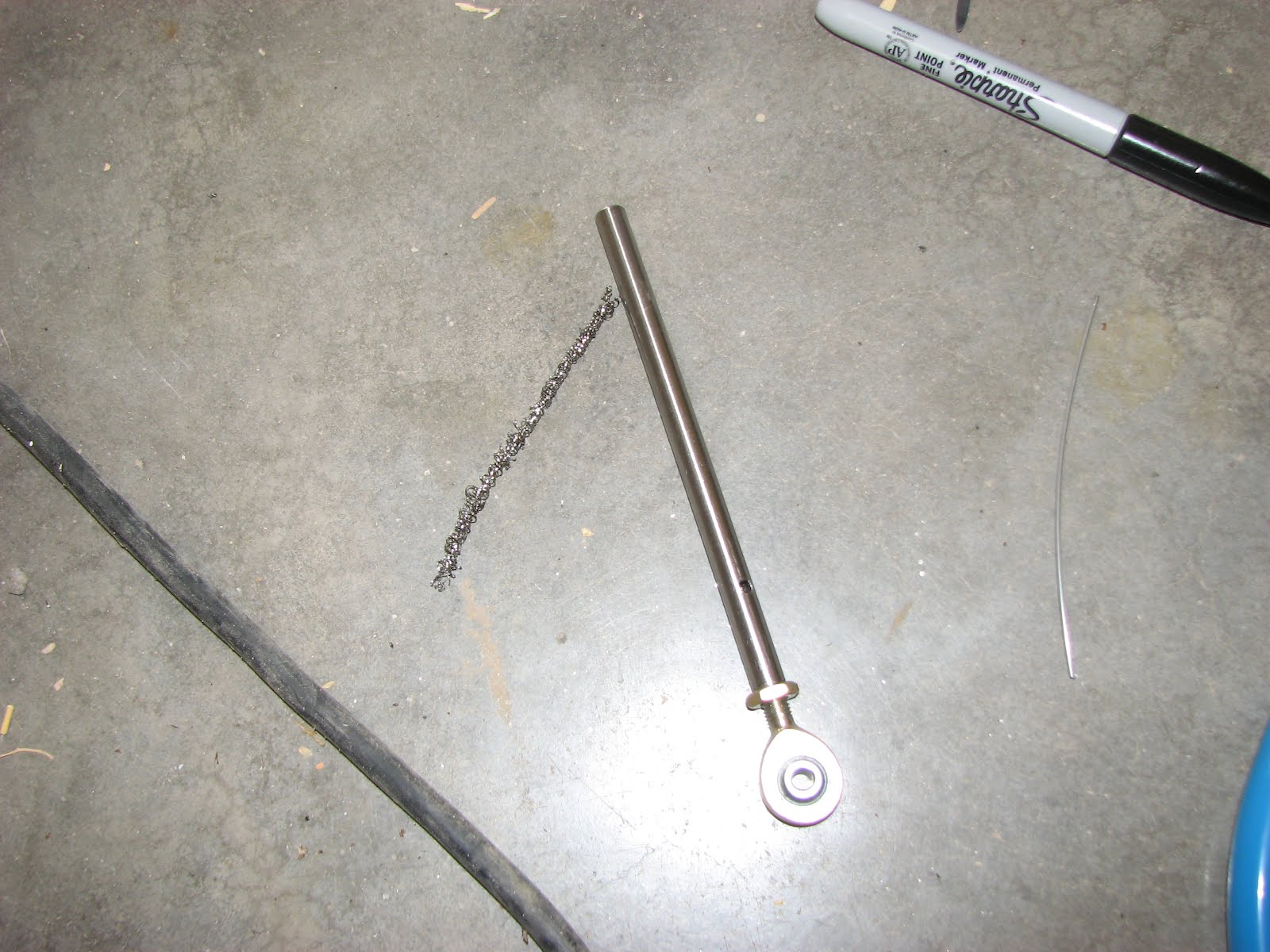
When I came home from the paying job I found two surprises waiting for me. One was the oil pressure sensor relocation kit.

The instructions are minimal, so I will take my time to figure this one out. I've never manufactured firesleeves, so I will have to research how to do this.
The other surprise was not such a pleasant one. I opened the heater door to see if the seal hat nicely set and it had not. Apparently the type of car wax I used has a chemical formula that kept the RTV for vulcanizing where it got contact. So, I had a bunch of smeary, grimy stuff to remove.

I cleaned it all up and tried again.

This time I used Boelube as a separation agent on the firewall. I hope this turns out better!
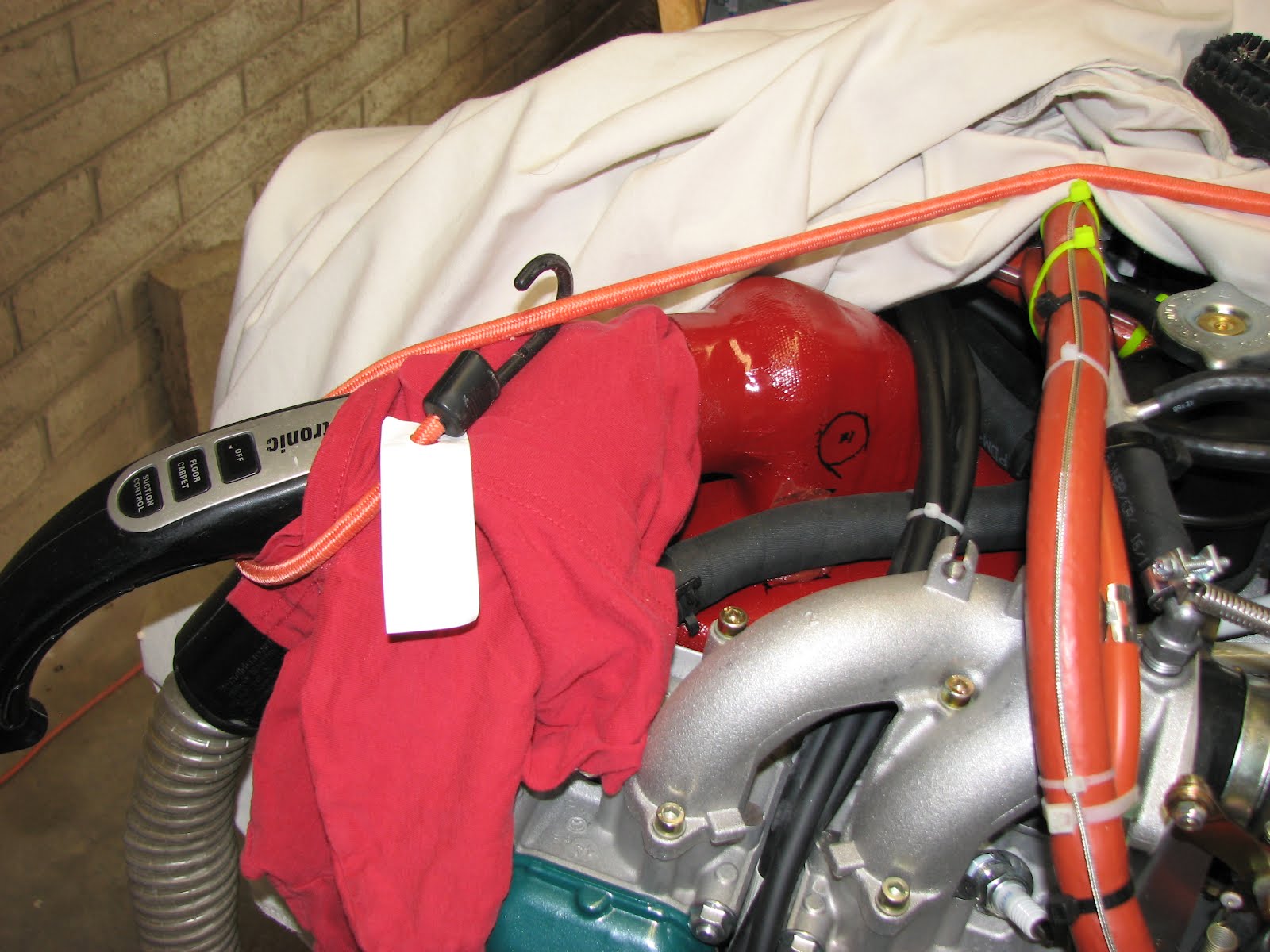
Next was the dreaded oil overflow tube. Dave had so much trouble installing this little clamp on the Gascolator that I couldn't convince myself to install a clamp where a cable tie appeared to do the same job.

The routing is a bit delicate in the upper part as the carb will have a n air filter mounted to it and that might then interfere with the tube. I'll have to check that tomorrow and see if it clears it.

Also, the hose pushes hard against the firewall shelf and I added a fuel hose on top of the PT tube to keep it from chafing.
The installation of the water reservoir was uneventful, but take a close look at the clearance between the bottle and the bar that holds down the battery. There's hardly any and so I might have to remove that bar again and remove some material.

As I couldn't install the radiator due to the failed RTV vulcanization, I decided to at least install the hoses on the opposite ends of their radiator attachment.

This one was the easy one. The lower one is a bad joke because it could have been installed any time sooner than now and it would have been much easier. Now, the accessibility of the water pump flange is almost zero.

I had to cut a cable tie to move the fuel pump drain hose out of the way and there is only one way, and one way only, how to install the hose clamp in a way that you can actually get to it to tighten it.

I am already dreading that I have to remove and replace these hoses in 5 years because they will probably still be badly accessible.
The final step was to install the clamp (again, with the help of a cable tie to close it while positioning the bolt).

I left it loose so I can adjust the hose in the clamp when attaching the radiator.
This is how the temporary routing on the right side looks like now:

Depending on the RTV results, I might be able to actually install the radiator tomorrow.
Things will get a little busy later this week and I will not have that much time to build this weekend as I am headed to Santa Barbara on Sunday. But I'll be back on Monday evening, so no big delays expected.