It was a fight of epic proportion, but I prevailed!
Let me report in proper order though.
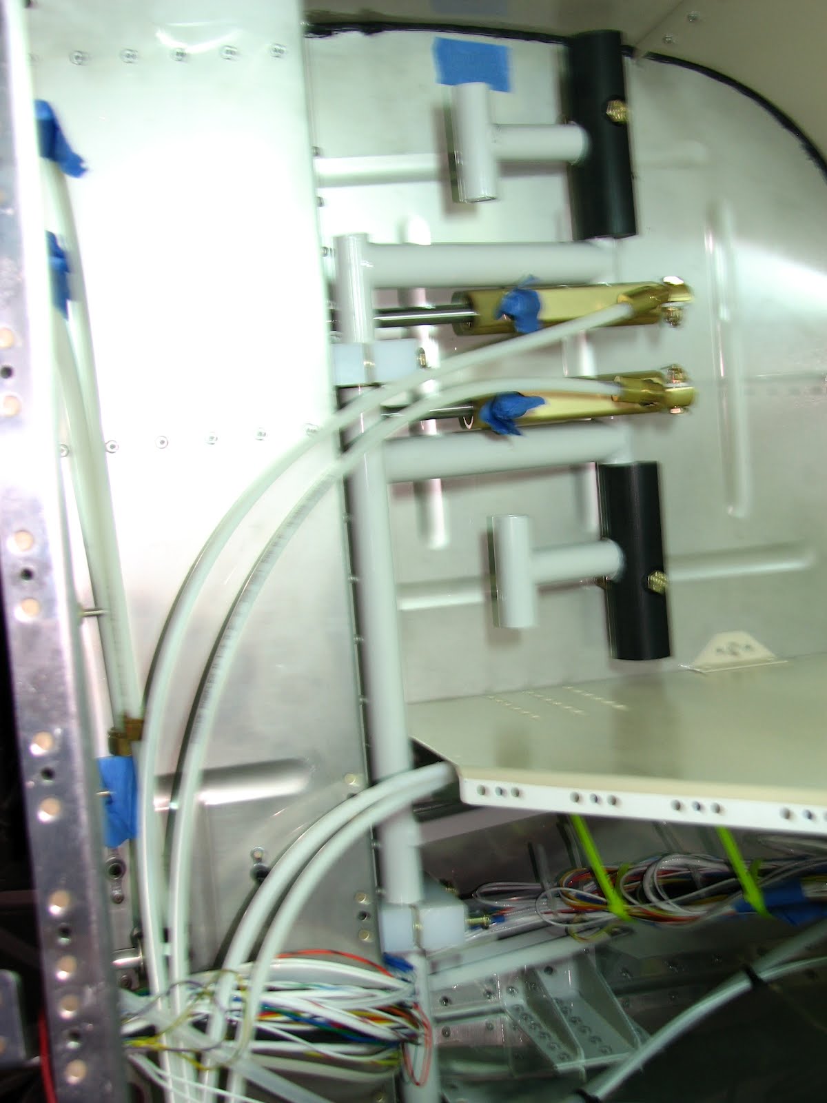
First, I worked in the tailcone. With the proper connectors from Ace I could hook up the PE static line to the stub that I had left from the previous static installation. This hose is now used for the pitot line. What made this task difficult was the little leftover stub. That one is made from Nylon whereas the new line is made from PE. The PE seems to stretch more willingly to slide over the hose extension piece. The Nylon was not easy to persuade. I used a bit of Baker-Seal on the Nylon barbs and a pair of pliers to get a firm grip on the barb while pushing the Nylon hose over it with the other hand. It worked put after a while.

Then I made the T extension that runs from the tapped static line in the upper center of the bulkhead to the ADAHRS static port. It's easier to hook this up outside of the tailcone. Then I cut the static line in 12 o'clock position and inserted the tee. I also had installed the connector before putting everything in the tailcone but I let the nut loose for screwing it onto the ADAHRS.
I also drilled out the ADAHRS bracket again and removed the nutplates. Then I located the screws and nuts that Van's asked you to use to install the ADAHRS and checked them for magnetism. Guess what! The screws as well as the nuts are magnetic. I decided not to install anything at this point and ordered a pack of #6 brass screws and nuts, along with some nylon washers to separate the brass nut from the aluminum flange to avoid corrosion.
So it was time to move to the front of the aircraft to install the rudder pedals. Oh what joy!
Some prep work came first. I taped the two tubes together in the hope to have it easier to control them inside the fuselage.
Then I removed the nuts and washers and put the bolts in from the other side. Because of me inserting the assembly sideways, I couldn't rely on gravity to help me keep the upper blocks in place. That's why left the bolts in. They have to get gradually removed in order to slide the thing in. There's hardly any room in there, so heavy cursing is in order!

If you do this sideways, focus on the upper block and cant the whole thing a bit outwards so this upper block is the first sliding under the shelf. As soon as the bolt blocks movement, remove one and move on until the second one makes contact. At that point release the cant and see that you get the center block in beyond the first bolt, then work on the lower block. It took me a while to figure this out and all that in awkward position, with waning light and no room to work, while holding the assembly in one hand (did I mention it gets heavy after a while?). The fact that I first had to clear the two short wires and the static line didn't make it easier either. After about half an hour of fighting and scaring my neighbor with my cussing, I had it in and one of the upper bolts some threads into the nutplate. I just hope I never have to get these out again!


I started the two upper and the two lower bolts until they started resisting (need a drop of Boelube each), then I removed the center bolts and installed the little wire support angle (page 31-13 or so) and engaged the two bolts in threads as well.
Getting that tie wrap around the wires and through the two holes in the angle was no fun. I think, I'd do that first, before mounting it to the plastic blocks had I to do this again.
It looks like I can finish section 27 (rudder pedals) and section 31 (basic wiring) tomorrow. That'd be a nice change over starting new sections all the time!


No comments:
Post a Comment