Showing posts with label vertical stabilizer. Show all posts

Sunday, June 3, 2012

Rudder Installed

In the morning I had the joy to remove the left and right torque arms. I put them on the work bench and prepared them for match drilling the belly side holes.

That was easy. Opening them up and drilling them through with a #12 bit needed a bit of thought. I chose the drill press for a straight path for the bolt that will later get installed.

With some Boelube the drill bit went right through without a hitch. After the deburring the pieces looked like this.

Installing them back in the belly, along with the torque tubes, was harder than taking them out. I hate those washers on the inside of a bracket. I glued them successfully in place with Superglue. That made it a bit easier.

After lunch I pulled the ridder cables through the aft bulkhead using the rope I had routed and affixed to the tail cone almost 2 years ago.

I temporarily attached those steel plates to the cable forks.

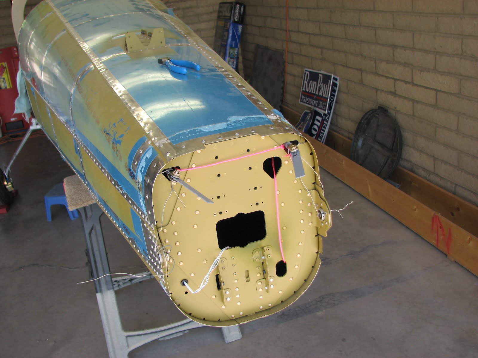
Then I attached the vertical stab to the tail cone. It is not an illusion that it looks like it's taller than the entrance of the carport. It definitely is too tall. I also had to move the fuselage way forward to clear the stab and the rudder, so I might have to take the assembly off again until I get to the hangar. I wouldn't be able to install the engine otherwise.

Here's a better shot:


Installing the rudder was a nightmare. The glued on washers wouldn't stay on because of too much lateral force on insertion and I couldn't get a finger and a bolt in on the top hinge. Fiddling with pliers didn't give enough grip to force the bolt in. After half an hour I finally succeeded by accident. This is probably the worst part of the assembly so far.

I centered the rudder with a string once it was installed. The strings follows a rivet line on the rudder and ends on each trailing edge of the stab. Measuring the distance between those two points divided by two gives you the center mark on the string. You also mark the ends of course. Then hold the end marks on the trailing edge and adjust the rudder with the tip of your nose until the edge of the rudder is on the marked center spot on the string. I verified by eyeballing that I wasn't all off and clamped the plates to the rudder horn.

In the cabin I had the pleasure to install Denny Myrick's gift he gave me at our last meet at the airport - his rudder jig! He saved me a lot of time building this piece. Thanks again for this, Denny!!!

I pulled pretty hard when tightening the ridder cables but it didn't feel like the left one was giving much. The right one came out significantly farther than the left one. So I checked on the inside if there was slack on the left cable. Nope, not as far as I can see.

However, when I unclamped them after marking, they looked like this.

I will have to check with other builders if this deviation is common or if I made a mistake here. So until then I will hold off on drilling them.
Update: Bill and Dave confirmed this is a reasonable difference that reflects the difference in the rudder horns on the pedals.

Not sure what next to do. Tomorrow I have to go back to the paying job and I believe rigging the stabilator is next. More fun with washers I believe.

Saturday, May 26, 2012

Rear Bulkhead Cut

The morning started by catching up on the left over from yesterday, riveting the stabilizer tip on.

And then the two pieces got stored away again until the rigging of the control cables.
The next step on the list was to modify the rear bulkhead to allow the tank to be permanently installed. I removed my old markings and applied new ones. The previous ones didn't take the existing screws into account and so the screws didn't line up with the existing ones. After this rather time consuming ordeal I was able to clamp the two back pieces together and see if they had roughly the right size.

As this turned out to be the case, I drilled, deburred, dimpled and riveted the two pieces together.

I clamped the back angle to the bulkhead and ensured that it properly aligned.

Here you can see the drill markings on the front. I used a punch to mark the position for the drill bit.

On to the drill table... Clecoed as I drilled. All the holes are #30s at this point.

All the holes line up perfectly in the back support angle. I must have done something right when calculating the positions of the markings.

I opened up the holes for the screws with a #19 drill bit and unclecoed the parts and deburred all the holes. Then I went on to cut the bulkhead. That's when I noticed that I had no clue if I could actually do it on the bandsaw.
Well, I couldn't! One cut could have been done but only on the wrong side which would have not allowed me to support piece properly during sawing. And this could have caused issues when trying to follow the line or even bent the metal. I decided to go manual on this rather delicate cut.

Why is there a saw blade in the previous picture, you might ask. Well, the hacksaw (sounds gross but the blade is a very fine one, so it's more a surgical tool than a real hacksaw) would only go so far - about 2 and half inches that is. The rest I cut by using a saw blade and my bare fingers to pull it through. I now officially understand the saying that not money nor time are the factors in finishing a homebuilt plane, it's will power.

Almost through. Look closely, the blade is at the last corrugation. At that point I was getting worried that the mechanical forces on the bulkhead that occurred from the violent pulling on the saw blade could bend the cutout just before breaking through. I decided to ply it safe and clamped the pieces together as well as the bulkhead to the work bench.

That made all the difference. With the forces tamed I could focus on finishing a straight cut to the end and the pieces came apart cleanly. I rounded the sharp inner edge in the larger part of the bulkhead and deburred all the edges. I was now able to cleco the back support on and see how much I had to remove from the shorter angle to clear the bulkhead frame. I shortened the piece, deburred the edges again and clecoed it back on to take on last shot.

I decided to dimple the screw holes and use K1100-08 nutplates plus one fancy one with one lug that will go into the corner. The order went out today but until later next week I don't expect to see any parts. I might have some K1100 left but I'm not sure if there are enough to finish the job.
Also I will have to work on the floor plate which I couldn't do today.

Friday, May 25, 2012

Tips Installed

Yesterday, when I wrote the outlook for today's work, I expected to be rather short of work than not being able to complete all the tasks I had planned to do. Trimming the rudder and vertical stabilizer tips seemed to be rather benign and a job to be completed in a few minutes.
It turned out to take me 5 hours to complete it. I started by emphasizing the scribe line for the initial rough trimming.

With the help of the belt sander I was able to quickly remove the excess material and get a nice fit of the tips.

The next step was to match drill the tips to the rudder and the vertical stabilizer. I started with the latter.

Then there was some more trimming to the tip of the vertical stabilizer required. The aft edge had to follow the edge of the metal skin. Again, the belt sander made a quick task out of this.

And then the process stalled. I had to temporarily install the rudder and connect it with the stabilizer. However, Van's must have used kid's labor to get these bolts in there on their SLSA. I have no other explanation that they ended up with a access space so tiny and claiming that they succeeded. It took me what like forever to get the bolts in there. Initially, I had even tried to get the washers in there but quickly succumbed to the inexplicable aggravation this attempt had caused in respect to the aforementioned tiny space. So I ended up inserting the bolts only and lifting the rudder slightly when checking for clearance. It's not really a delicate tolerance to begin with.

About 8 or 10 times of removing the tip, sanding it a bit more and reinstalling it, I was at the required fit of 1/8" clearance to any edges over the full travel range from stop to stop. I mainly used the belt sander again but also the Dremel tool with the drum sander in a few spots.
I finally riveted the tip to the rudder. Holding off on the stabilizer at that point as I discovered that the primer I had sprayed about two years ago was a bit thin on the top rib. As this one would get exposed most to environmental influences, I decided to top the coat with some Napa primer and let this dry before riveting the tip in place.

That was my day in the shop. I assume tomorrow will then take care of the rest of yesterday's outlook. This was to work on the rear bulkhead and floor panel. I am not planing for anything else at this point as this got delayed so many times before already.

Saturday, May 29, 2010

Hinge Nightmare


After the primer had dried over night I started the shop day by putting together the upper hinge assembly to finish the V-Stab.
Clecoed everything together and then rivetted the thing with AD4 rivets. After doing the three closest to the bearing I tried it to see if the bearing was still moving freely.... and: Damn! It got stiff again and would hardly move at all. The same problem I had before.
Thanks to the Van's Airforce website I had found out that the only reason why the bearing could lock up is pressure from the cage surrounding it. I checked the assembly again after drilling out the three rivets and I found a hint of primer on the inside of the assembly right where the bearing is sitting on. I could hardly believe that this little could have such a huge effect but I was getting desperate and in lieu of another clue I went on and scrapped off the little paint spray dust that got on it. Once it was all shiny on the milled surfaces again I put it back together started rivetting and .... you wouldn't believe, it worked!. I set all 5 rivets and the bearing was moving freely just like before when the hinge had been clecoed.
So, be careful with the milled surfaces and make sure they are totally plane and clean before wasting your time on it!
The image shows the finished upper hinge assembly next to the primed parts of the previous attempt (notice the thick layer of primer in the bearing cut outs) and also visible are the unmodified parts of the hinge as Van's sent me an extra set of parts.

Screwing on the hinge onto the V-Stab was a piece of cake after that. You'll see pictures of the whole assembly when I trial fitted the rudder spar to the V-Stab.

Friday, May 28, 2010

Preparing the Rudder Ribs


So Van's had sent me the replacement parts to rebuild the upper hinge assembly for the V-Stab and so it was prep time again. As I wanted to prime the parts I took care of some more parts as the rudder ribs got drilled anddeburred and were ready for priming as well. As my Cortec primer finally arrived I wanted to use this expensive stuff and see if it really works wonders or not. This type of primer (Cortec VcPI-373 and the surface preparation with Cortec VcPI-440) is supposed to be applied with a spray gun and I had to learn how to use this tool before I felt good enough to try it on the real parts. I'm still learning the little details but for primer work I'm doing good enough.
I have to say that I'm pretty impressed by the Cortec stuff. Environmentally not too harmful, no nasty fumes and still a great result on aluminum.

Thursday, May 20, 2010

V-Stab finished... almost


And so I finished riveting the skin to the V-Stab the other day. Nothing surprising happened (I consider this a good thing). The only noticeable thing that happened was that my shop A/C broke and with over a 100 degrees it's a bit too hot out there to work without it. A replacement unit is on the way (the first just got 3 days old before it broke).
Fitting the nose of the V-Stab looked like a real bad job but when I screwed it on it just pulled itself in place. NICE!
So that was it with the V-Stab - except for screwing on the upper hinge assembly which I can't do as the parts are still on their way from Aurora. The previous parts couldn't get riveted without causing the bearing to freeze up,
On of the first assembly steps for the rudder is to trial fit the hinges with the rudder fittings and I don't want to get too far ahead this time. There might be a reason why Van's wants you to do it before assembly.
So, I'm limited to deburring and finding a place where to store all those parts I will eventually have assembled ...
Overall time for the V-Stab was around 35 hours.

Wednesday, May 19, 2010

Stabilizer skinned


In the morning, before going to work, I finished squeezing the last 9 rivets for the nut plates. I just couldn't let it sit like this.
In the evening I put the skin on and the fit appeared to be good. So I continued clecoing the skin on, beginning from the leading edge on one side. Everything looked good but I wanted to be sure and so I turned the Stab and tried to cleco the other side as well (raising the Stab on some coffee cans to clear the clecos from the workbench). After I did that I was pretty amazed that it looked like I was already ready to rivet the skin on - but then I noticed little buckles near the leading edge in the front areas of the ribs. It wasn't the radii that had been excessively trimmed in the previous steps, it appeared to the be the ribs being too long and the upper front pinched into the skin. So I took the skin off (oh my, why did I have to send my air cleco tool in for repair TODAY?) and the scratch marks on the inside verified that it was the rib webs being a bit too long. The die grinder took care of that and I made sure I wouldn't have to do this cleco party again! Scotch-Brite polishing, re-priming the rib noses, priming the inside of the skin, particularly where it got scratched and along the rivet lines didn't take long.
Then re-skinned, aligned and adjusted and finally riveting started. I got as far as finishing one side and starting the leading edge on the opposite side. The process is a bit slow as you have to go one by one in the leading edge area because of the high tension there.
Anyway, the V-Stab is almost finished!

Tuesday, May 18, 2010

VS skeleton ready, skins prepared


Tonight I finished the assembly of the VS skeleton, and put it aside to make room for the VS skins. Final drilled the #19 holes in the front and main skin and dimpled the nut holes and the rivet holes for the nut plates. I'm not sure how straight the edge of the front skin has to be that has to be trimmed after removing some excess material. I was very careful when removing the material but the edge doesn't seem to be completely straight. We'll have to see how that will look when the two skins will be put together.
When riveting the AN426AD3 rivets for the nut plates my hands grew tired on the last batch of 9 rivets and I had to give up for the night as I didn't feel I could still do a good job squeezing them. Those rivets are small but a large number of them gets me tired after a while. I think I'll be dreaming of a pneumatic rivet squeezer tonight. If only they'd be more affordable...
Just summed up my worked hours on the VS ... about 26 so far.

Sunday, May 16, 2010

2 steps forward, 1 step back


It was a busy weekend and I had a lot of fun, until I discovered that I got carried away and riveted way too many holes that weren't supposed to get riveted just yet. Well, at least I had a lot of practice with my rivet removal tool - oh, how much fun I had!
But there is hope! It seems I am learning from my mistakes as I didn't repeat the same mistakes on the left side of the rear spar, so the caps went in well and also the countersinking seemed much better this time.
I am still having trouble with the upper hinge assembly, as the bearing seizes when I rivet the brackets. The lower hinge worked just fine, but the upper one I riveted 3 times before giving up. I sent an email to Van's Tech Support.
The primer rattle cans arrived and I started priming the first parts of the vertical stabilizer that were in the queue for assembly, I also started riveting my first pop rivets. That Avery gun worked great and I had so much fun that I just riveted along. Unfortunately, I riveted much more holes as I should have, but I am repeating my self. After removing the unwanted rivets it looked like I got hardly anything done besides burning time...
Fortunately I spent Saturday at Aero Fair in Payson, AZ (KPAN). The flight was a lot of fun and passing Apache river and Roosevelt Lake was very impressive. To clear the mountains in thermal conditions I flew up to 9500 ft. I've never been that high in my little butterfly LSA :-)