Showing posts with label Section 29A. Show all posts

Thursday, May 24, 2012

Waiting For a New Servo

I received the new Control Module from Van's yesterday thanks to $40 for overnight shipping. So I could verify this morning that it didn't change a thing. The problem was exactly the same as it was before. The CM was not the culprit. Sigh!
So back to measuring and trying to disconnect and swap wires. At a moment I thought I had it. I had disconnected the SV Net 2A/B pins from the Options plug as I had a hint from the electrical diagram that the pins might be swapped. At least that's according to the plan. We know by now that reality might be different. So I diconnected the pins to see if they maybe interfered with the bus operation. At first it looked like it.

All wired up and jumpering the bus to the AP 74 wires again. That resulted what looked like victory:

All 5 devices recognized and correctly behaving all at once. Toggling the AP switch, turned the servos and and off without affecting anything else. However, after a while I noticed that the EMS sporadically was shown as offline only to come back online a second later. That all happened without me doing anything but watching he screen.
After a while I turned the system off, let it rest a bit and turned it back on. On the second power cycle one servo stayed offline regardless of what I was doing. Everything else worked. I put all the pins back in their spots, removed the bus jumper wires and brought everything back to the state when I first tested the system. It all worked without any problem, only that one servo, the pitch servo, stayed dead.
I called the Dynon Tech Support and they told me to send the unit in after they sent me a replacement servo. I believe that this servo was faulty from the beginning, causing the problems I was seeing. That explains why the ADAHRS and the EMS were disabled as soon as this faulty servo came online or was just connected to the bus. Why the other servo did work I don't understand but we will soon see what happens when I attach the replacement servo.

I also verified that the wires were correctly hooked up. Well, sure they were. The servos did work after all and I ran a few calibration tests with the wiring.
After "solving" my Avionics problem I went back to other waiting tasks at hand. This was the map box. The yoke had arrived and I happily squeezed the last rivets.

This 4" yoke is quite massive and you can feel that it's getting springy at that length even with AD3 rivets. No way you could reliably squeeze AD4 rivets with that, I believe.

I installed the Camlock receptacle with another two AD3 rivets.

And then riveted on the door, pulling the rivets from the inside so you wouldn't see the ugly shop heads.

That finished the map box installation and covering the holes was finishing the assembly of the right panel.

All I had to do now was to install the panel in the cockpit which finished section 29A.

While I am waiting for the servo, I will probably work on trimming some fiberglass tips and also cut the rear bulkhead and the panel floor. I might even look into the gear leg installation or put up the temporary garage as my truck will get expelled from the carport for a while.

Saturday, May 19, 2012

Avionics Almost Completed

With the current heat, I should have definitely started earlier. However, I was tired from the paying job and was working late to help with fixing a problem on the mountain where the telescope is located. So, I felt I needed my sleep and didn't get to work on the plane before 9am.
Last night I had tried to touch up the part of the center panel that looked a little funky after the previous paint application. I should know better never to touch-up flat paint as it just won't work. And it got confirmed again. The area that looks funky has now been increased in size but the initial problem has not really been improved.

Because of the location I decided against respraying the whole center panel. Instead I went ahead to use it and install.
I also know that this paint improves its sheen after two days of curing, so it might be less visible after that and in the end, I just really don't care that much about looks.

As you can see I decided to install the GPS mount before certification. Reasoning is that 42D explicitly gave me the option to cut out a section on the center panel to install my Garmin x96 GPS. Mine is a Garmin Aera 500 that has the very same interfacing that the x96 had. I will however, just put the mount on and not attach a GPS to the mount. Wiring of the mount can also be done exactly following the instructions in 42D, so I don't feel I am modifying anything here, just following the instructions and applying them to the case at hand.

For now I didn't connect the mount yet, as I will need some time to study the diagram and see where the best hook-up point is. I believe it is in the GPS plug but I want to make sure.
I went on to install the radio, or better, the tray for the radio. The tray is prewired with the Communication harness and only needs the antenna plug connected to it. However, this turned out to be more complicated than it read. The problem was that the routing of the antenna cable is very distinctive and after installing the tray there is hardly any room around the tray anymore. This thing really fills up the avionics compartment!
So, to pull out enough antenna cable to route it without bends, I had to cut a lot of the wire ties in the tunnel and make a medium mess down there.

Then I was able to locate the tray in its approximate position on the tray support angles.

Look how tight the wiring routes around the tray. This was taken before I collected some of the stray wires and tied them down to avoid chafing.

The screws went in ok, easier than I thought, actually - but be careful, read the instructions carefully and notice that the washers for the #6 screws at the center panel brackets got BETWEEN the tray and the bracket.
Sliding the radio in was easy and everything fit. However, it took me a while to understand how the locking cam mechanism works. Initially I had it tightened all the way and was wondering why turning the cam wouldn't lock the radio in the tray but bend the tray out a bit. You have to turn the cam counter-clockwise as you would unscrew a screw a bit before attempting to lock the radio in place. Then it will catch on the locking notch correctly and you can carefully tighten it a bit. Remember though, it doesn't take much to get 4 ft./lbs.!
When I wanted to install the left panel piece, I ran into some legacy problems. I must have accidentally picked the wrong nutplates when installing them in the left and right canopy ribs. I think the ones I installed where for AN3 bolts and it clearly says I needed K1000-06. Both nutplates are in one tray in my magazine, so I must have been tired when pulling them out of there. However, I drilled them out and installed the correct nutplates within a few minutes.

No big deal, everything was accessible.

And then, like magic, that left panel went in without any problems. It's amazing how easy things are when you just do it right...

I slid the SkyView in and added some blue tape to hold down the screen protective plastic and cover the buttons a bit from dust getting inside too easily. I used the deeper Fastenal screws that were mentioned on VAF a few days ago so to not round out the provided flimsy looking screws.
BTW: I should mentioned here, as you can see the front of the fuse panel, that I replaced the 2A starter fuse with a 3A because Bill H. had measured that the current for that relay is too close to the fuse value and it might burn it during normal operation.

I used the lower of the two SkyView Network plugs as the upper one is easier to get at for later extension if that would ever be needed or desired.

FlightCom 403, ELT remote control and the APDC button were installed, to complete the left panel installation. I ran the ground wire of the ELT to a corner screw of the Ignition module and installed the screw holding it down with Loctite blue. I appeared to be easier to do that running the short wire all across the other harnesses.

Looks really nice from the pilot seat too.

On to the right panel and the installation of the map box. I have the recommended 3" yoke for my squeezer and I had the desire to get a 4" one before but could resist it then. Now, I gave up. Despite my extra cutouts in the panel, I cannot reach 6 of the rivet holes and I HATE those CCR264 rivets. I do not want these being visible on my panel, so I ordered a 4" yoke now to squeeze all of the rivets.

I got enough rivets set to continue with the match-drilling steps for the two screws that connect the deep end of the map box with the panel base.

There were two holes already punched in the panel base that looked like #30. These are the ones you are supposed to open with a #19 bit in this match-drilling task. I used a wooden block to avoid drilling into my hand again and to safely hold down the map box during the drill process.

I deburred the holes and sat the right panel aside as I won't install it before finishing riveting the map box on.

This task concluded an 8.5 hour day working on the plane and the avionics are all installed. I need to hook up the two antennas on the belly to make it official but I can't do that before putting the plane on the gear legs.
I have yet to install the fuel pump switch and hook it up to the EMS plug, I also have to connect the power supply for the GPS mount and have to find a way how to temporarily provide current to the system so I can power it up and see if I basically get the correct responses. The servos and the ADAHRS should get detected, so does the GPS antenna. The radio could get tested with a temporary antenna connection and even the power supply for the backup GPS could get verified. The plug to connect the fuses to the battery seems to be part of the Powerplant kit because I haven't seen anything like that yet standing out.

Saturday, May 5, 2012

Section 27 Completed

I almost completed two sections today but because of the OAT probe supposed to get installed on the left side where the fuselage is resting on, I couldn't fully complete the second one yet.

The day started early due to the increasing heat. We are in the low 90s today. I started by tightening those nuts that hod the rudder pedals to the shelf. That's when I noticed that I couldn't bottom out the right pedal. It was interfering with the fuel return line at the mounting point of the ruder cables. It is really very tight in that tunnel. No room has been left unused. Fortunately I could bend the return line a bit to give the rudder arm enough clearance. I also tied the cable bundle to the return line to avoid interference with the wires and the rudder arm on the opposite side.

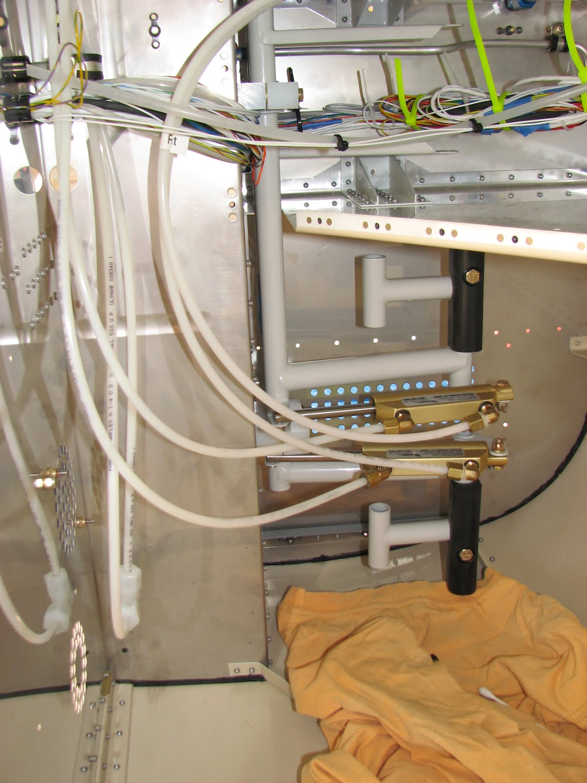
Then I hooked up the lines to the brake reservoir...

... and to the actual brakes.

Then I went in the shop to start the work on the left and center panels. The left one needed some extended countersinking for the marked nutplate holes and for the mountain screws.

I also tried to find a home for my PCAS and I was hoping it would fit in that little spot above the ignition control. I added some markings on the panel to see how much clearance I had - if any.

As you can see, it's just not enough room to go there. I tried the right panel as the top center space will be reserved for the backup GCS.

Yep, that'll do! The work on this will have to wait until I have received my instruments. The Winter ASI with 510 degree arc is on special order as I wanted to get the markings done by the factory. I don't think the ASI will get here before next month. The altimeter should get here by next week. I found install sheets for Winter online, so I should be able to drill the mounting holes without having the actual instrument.
But before that I went back to the left side. The APDC switch hole had to get drilled. Positing was first.

And then it was drilled, using a #30 pilot hole and the step drill to open it up. All done on the drill press.

Please note that the plans are incorrect in asking for a 1/2" hole to be drilled. A 7/16" for the switch is totally sufficient.
It was time to countersink all the holes for the mounting screws AN507 #6.

Then I opened up the hole for the fuel pump switch that I intend to put where Van's had me put the APDC switch. I still think it's not easy to get to that location with the throttle being in the way. However, this is perfect for the fuel pump switch as this is usually supposed to be and stay on.

Back to the left panel. The stiffener angle had to get riveted to it. However, the APDC switch mounting nut would likely interfere with a small part of it. So I marked the area that should get removed.

The material was quickly removed with the SB wheels.

Then I riveted on the angle and the nutplates in the left and center panel.

Now it would be time to put the final finish on but I am not yet decided what to do and so I put them away for later. The right side needs the cut-outs done first anyway.
Looking ahead in the gear section, I found that a few steel parts could use some priming.

Then I spent some time cleaning up in the tunnel. Tightening cable-ties, snipping off the ends and final routing the static line in the tunnel.

The tailcone is still waiting for the brass screws to arrive, so except for tightening the cable-ties a bit, I left it alone.

I'm not sure what to do next. I could go back to the canopy but final finish would require the fuselage to be upright. I've identified some parts that need painting in the interior color and I still have some of the Steward paint left. Maybe I go ahead and do that, so it can cure over the hot and dry weekend.
I also still need to fit the end fairings for the rudder and the vertical stabilator. So that's also a choice for tomorrow.
Either way, I am getting close to putting the fuselage back on its belly.

Sunday, April 8, 2012

Catching up on the Panel

With the new Avionics Kit I also received updated plans for section 29, now called 29A. While the resin on the canopy was still curing, I wanted to do a bit more work and so it seemed reasonable to see what had changed in this section 29. I didn't finish 29 either, so I wanted to get a better understanding on what I had already done and what had to yet get done in the updated 29A.
One of the tasks that seemed doable with out access to the panel (Remember? The canopy is kind of in the way...) was assembling the map box. This task appeared quite labor intensive and was filled with little traps so I had laid it off for now. This was a good decision as the 29A section revised the map box assembly and also asked for new updated parts (the right panel and the mapbox door) that I had already pre-ordered, thanks to Bill Hollifield who had told me about these changes ahead of time.


This shows the tricky step of match-driling the hinge and the door. It really was not big hassle and so I believe that the new map box door that had a little template attached to it for proper alignment, made all the difference.


A little bit of countersinking added to make the surfaces smooth and I soon had this.


Finishing up the rivets on the map box door was easy.


The door was then ready for painting. I'm not sure what to do with the panel at this point, so I just put it away and assembled the actual map box.


And countersunk the holes for the screws that will attach the panel to the fuselage. These screws were pan heads before but Van's decided to use flat heads now and so these holes need to fit the head of a AN507C632 screw.


Now the right panel was ready for painting too - laid aside as well.
It was time to look at the bridge of glass I had built yesterday.


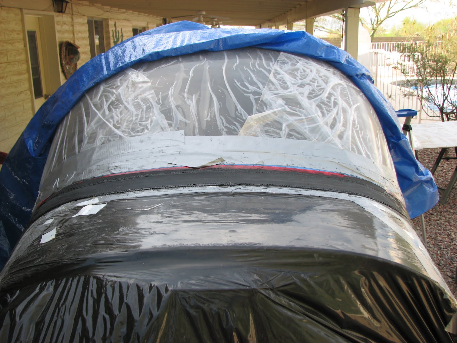
The weave showed through and appeared to be quite rough. Also I didn't like the fringed edge towards the canopy that wasn't as clean cut as I wanted it. I decided to mix some epoxy with micro-balloons and dye and fill it now, before sanding. There were also some areas that needed a smoother transition and the thick mix of resin appeared great for this purpose too.
I immediately covered the wet areas with Dacron again to make it even smoother.


This time I had waited until the fuselage was in the shade before working with epoxy but there was so much to fill and the resin started gelling while I was just finishing up. There is really not a lot of time to work with this stuff. Anything bigger than the skirt and it would be too much for one run.