Showing posts with label Section 11. Show all posts

Sunday, June 10, 2012

Trimming the Canopy Skirt - part 1

Why was I so quiet yesterday? I was building a house for my truck so it would bake out in the sun while it is exiled from the carport.


This job took most of the day and working in the open sun didn't make it easier at all. After finishing this I just let it be good and enjoyed the afternoon cooling down in the pool.

Today, I was faced with yet another loss of internet access due to a low signal at the hook-up point. I have never experienced a worse cable service than with Comcast. However, I cannot switch as Cox and Comcast have conveniently divided the city up in half and they do not compete in my area. Sounds like a cartel? Sure, that's because it is one. No third provider would provide internet speeds that I could live with, so I am stuck with this horrible service at an outrageous fee.
So, while waiting for the cable guy to come buy (they could just open an office on my street to save them and me some time), I took the stabilator off again. Not just because I wasn't happy with the cables and the threaded ends in the turnbuckles but also because there wouldn't be a way to really work around the stabilator. It's just too big and I will store it for now until it will get reinstalled when the plane is at the hangar.

Then I started the much dreaded job of trimming the canopy. First I had to cut out the trimming template and apply it to the canopy "horns".


Marking the outline of the template presented a challenge as I had chosen to dye the fiberglass black and none of the Sharpie's would leave a good mark for trimming. Fortunately, my wife loves scrap-booking and she had a silver pen that worked great on black. I was a bit conservative when marking the outline. First I followed the template, then when it was removed I added about a 1/4" in the front as a small deviation in the back where the clecos were, could create quite some offset in the front. I didn't want to be cutting off too much before fitting it.


The center section was first traced with electric tape and then also marked along the edge with the silver pen. The tape made it easier to correct the alignment as well as providing a nice straight edge.


I did a rough cut with a 6" cutting wheel, yeah, the thing that cuts through steel. That worked pretty well, you just have to be very careful and get a good grip on the thing.


The rough cut was followed by a finer one using the high speed angle die grinder. That tool sucks more air than the compressor can provide so I had to give the pump some rest once in a while to cool off.


Remember how I had a problem with some duct tape getting baked on the layup in the center section? Well I removed that today too by using the straight die grinder with a hard Scotchbrite wheel. It was pretty easy actually. Sorry, no photo of that one.
I also noticed another problem I had created myself when running out of time doing the center layup in the open sun. The lower layer had already set up and didn't connect too well to the new layup so I found delamination along the edge in some spots. I injected some fresh resin with a syringe and a thin needle (I bought this stuff for filling the rivet holes in the pop rivet heads) and clamped the leading edge together until it would cure.


The cable guy showed up during the trimming and figured out that the hook-up point signal level dropped quite a few decibels since the last time and that the signal was way below norm anyway. He requested that the amp in the service station for my area would crank up the power. He also replaced some low quality fittings as he called it and the signal came back up to levels the modem could work with until the amp would help to bring it up even further.
Let's see how long that will last. The last time a cable guy was working on my signal levels was just 14 days ago...

It was too late in the day to do the fine trimming and I have to see when Elizabeth has time to help me putting on the canopy. I want to put it on at least once this week so I know how much more trimming I have to do. I might just have to fill the brake system with fluid now as there's not much more I can get busy with during the week.

Friday, June 8, 2012

Stabilator Installed

In the morning I passed my ground part of the BFR, the flying part had already happened and so I'm current again.
Back home I got to work on the stabilator. With the sawhorses and some additional stuff to prop it up enough and a bit of patience the stabilator came on pretty easy.


Some noise next to the driveway caught my attention.


A baby quail following the rest of the crowd and Mommy- I must have disturbed them. The eggs it passed were quail eggs that didn't hatch.
Back to work. Connecting the cables to the horns was actually easy despite the washers that had to get squeezed next to the horn and in between the forks.


Then I took somewhat more than half an hour to put the large cover in place that holds the bulkhead in place when the cables get tensioned. There are really a lot of screws going into this thing!


Now the second turnbuckle went on both sides of the cable ends easily. I tightened them by feel and checked both cables with the tensiometer. It's the blue scale that applies here and the reading is at the 6 o'clock position. Right on 40 lbs. I should mentions here that Van's got back to me about the groove problem. Reality is right and the plans are wrong. They said "they had not gotten around to correct the plans yet" and provided me with a link to VAF where the grooves were discussed before. So is VAF now the official Van's Tech Support forum?


However, taking a close look at the cables and their routes through the belly, I was not happy. Not happy at all! It seems that the further to the front the more the cables want to chafe, at the edges of the holes they are supposed to pass. The upper one is particularly bad and is indeed touch with quite some force and the very front hole. There's no way of adjust anything in that respect so I am a bit at a loss here.


Also, all the cable ends are outside of the turnbuckles more than the three threads Van's was asking for. If I would screw them in deeper, the tension could easily be double the requested amount.


The elevator feel on the stick is nice though. No feeling of sawing the bulkheads in half, no chafing noise or anything. I will ask Van's what they think about this but I sure won't get an answer before Monday. Also if someone here has a comment, please leave a message with your thoughts!
I will have to take the stabilator off again anyway as it is way too big to work around in the carport. The same is probably true for the rudder but only because the entrance is to low to allow the fuselage to get pushed back far enough to have enough room for the engine installation. And I do want to have the firewall inside the carport and not halfway outside in the sun.

A bit frustrated about the results, I resorted to stuff I can control. I riveted some nutplates on the tunnel cover that will hold the flap handle arrestor.


That at least turned out very nice.

Tomorrow I will take the stabilator off again and store it until it gets hauled to the hangar that I will rent starting next month. I believe I might build one of those temporary garages/sun-covers so I can get my truck out of the sun. If there's still time I will start the trim work on the canopy.

Sunday, June 3, 2012

Rudder Installed

In the morning I had the joy to remove the left and right torque arms. I put them on the work bench and prepared them for match drilling the belly side holes.

That was easy. Opening them up and drilling them through with a #12 bit needed a bit of thought. I chose the drill press for a straight path for the bolt that will later get installed.

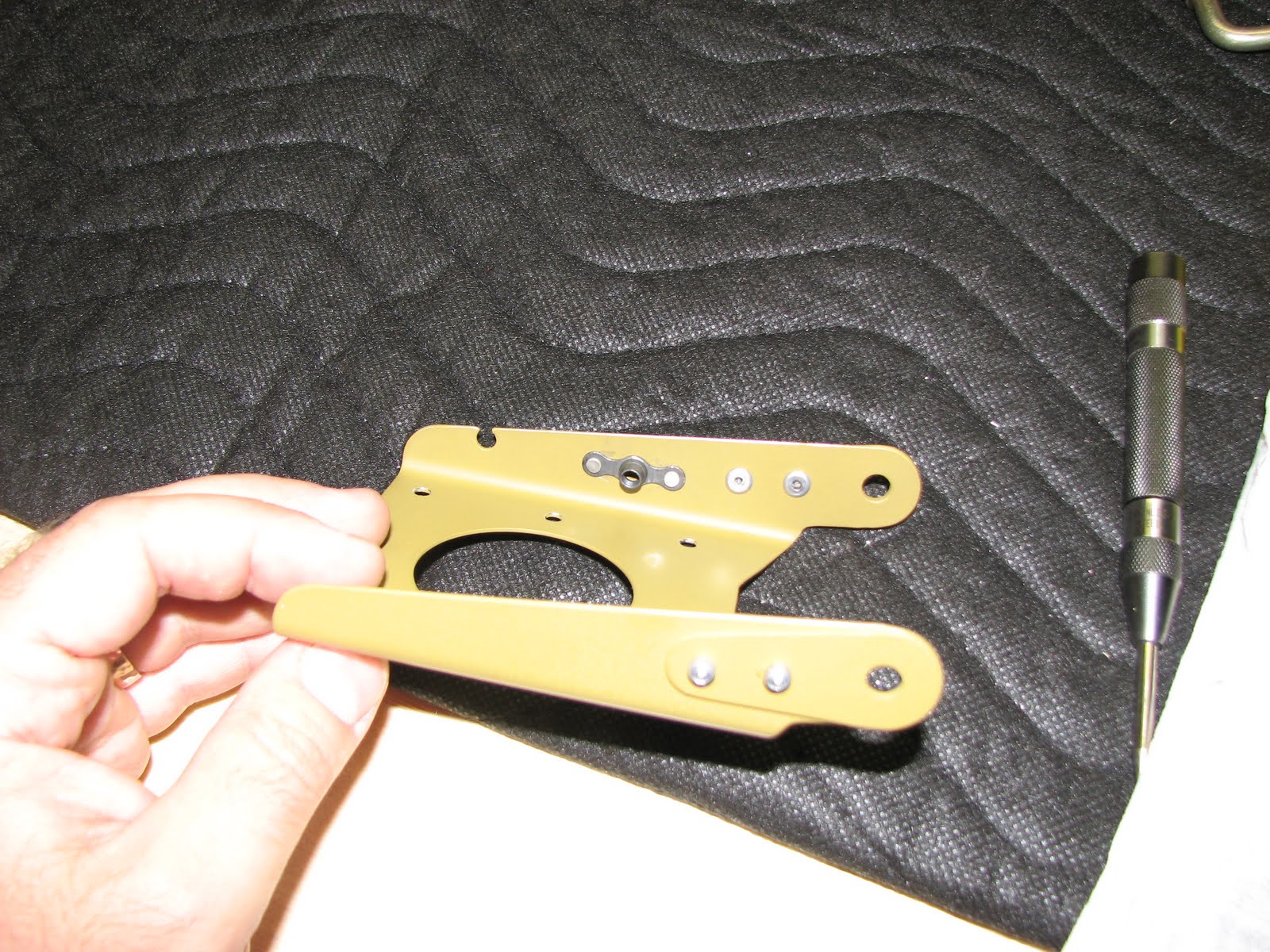
With some Boelube the drill bit went right through without a hitch. After the deburring the pieces looked like this.

Installing them back in the belly, along with the torque tubes, was harder than taking them out. I hate those washers on the inside of a bracket. I glued them successfully in place with Superglue. That made it a bit easier.

After lunch I pulled the ridder cables through the aft bulkhead using the rope I had routed and affixed to the tail cone almost 2 years ago.

I temporarily attached those steel plates to the cable forks.

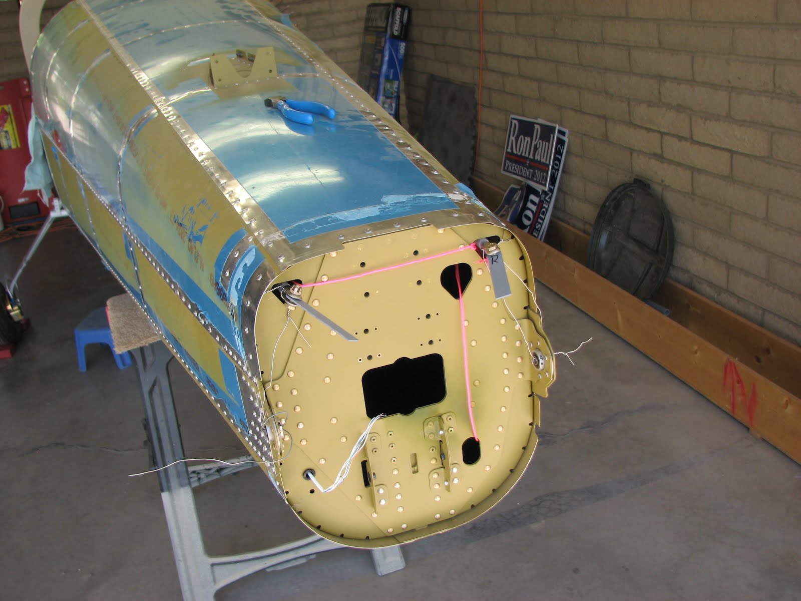
Then I attached the vertical stab to the tail cone. It is not an illusion that it looks like it's taller than the entrance of the carport. It definitely is too tall. I also had to move the fuselage way forward to clear the stab and the rudder, so I might have to take the assembly off again until I get to the hangar. I wouldn't be able to install the engine otherwise.

Here's a better shot:


Installing the rudder was a nightmare. The glued on washers wouldn't stay on because of too much lateral force on insertion and I couldn't get a finger and a bolt in on the top hinge. Fiddling with pliers didn't give enough grip to force the bolt in. After half an hour I finally succeeded by accident. This is probably the worst part of the assembly so far.

I centered the rudder with a string once it was installed. The strings follows a rivet line on the rudder and ends on each trailing edge of the stab. Measuring the distance between those two points divided by two gives you the center mark on the string. You also mark the ends of course. Then hold the end marks on the trailing edge and adjust the rudder with the tip of your nose until the edge of the rudder is on the marked center spot on the string. I verified by eyeballing that I wasn't all off and clamped the plates to the rudder horn.

In the cabin I had the pleasure to install Denny Myrick's gift he gave me at our last meet at the airport - his rudder jig! He saved me a lot of time building this piece. Thanks again for this, Denny!!!

I pulled pretty hard when tightening the ridder cables but it didn't feel like the left one was giving much. The right one came out significantly farther than the left one. So I checked on the inside if there was slack on the left cable. Nope, not as far as I can see.

However, when I unclamped them after marking, they looked like this.

I will have to check with other builders if this deviation is common or if I made a mistake here. So until then I will hold off on drilling them.
Update: Bill and Dave confirmed this is a reasonable difference that reflects the difference in the rudder horns on the pedals.

Not sure what next to do. Tomorrow I have to go back to the paying job and I believe rigging the stabilator is next. More fun with washers I believe.

Saturday, August 28, 2010

Trim Servo and Arm Assembled

The crimping pliers arrived in time on Friday and they are really a good bargain considering the high quality and comparably low price. So, if you are considering getting some, take a look at SteinAir's pliers before making your choice.
The crimping was real easy and I finished the wiring on the aft tailcone as well as on the trim servo.


The final assembly of the actuator arm for the trim servo didn't reveal any surprises either.


I later found out that I messed up one crimp on the servo that I will have to redo when I order another male spade connector from Van's. I'll probably wait with that until I have something else to order with it as shipping a 40 cents part is ridiculous.

Now I stored these parts away until I get to final assembly.

Thursday, August 26, 2010

Van's is busy!

It appears Van's business is thriving! Since I ordered my fuselage kit and them cashing my advance payment check early August, I hadn't received a confirmation and schedule letter yet. I asked them via email if it got lost or if they hadn't sent it out yet. Barbara took two days to just answer my email telling me that they are behind on these letters and the scheduling as they have so much to do.
I am glad at least they are having an increase in sales! That ensures they will still be there when I need some parts in the future. Bad part is I don't know when the fuselage is going to arrive but by then I should be still busy with my wing kit.
No problem!

BTW: I should get my crimping pliers before the weekend to ensure that I can play around with those connectors and I should be able to test the trim servo then.

Sunday, August 22, 2010

When everything goes wrong ...

Puh, that last session in the shop was quite hard to take. Pretty much everything went wrong.
At first I wanted to continue on the trim servo assembly and crimp the connectors onto the wires. The day before I had stopped by Harbor Freight and grabbed crimping pliers as I have always preferred to solder instead of crimping, so I didn't have any yet.
The tool looked cheap, was cheap and turned out to be completely wasted money. The pliers are so flimsy they didn't even put a dent in the barrel of the connectors. I am now waiting for real pliers to arrive from SteinAir.
Well, with this operation stalled, I moved on to put together the actuator arm for the trim tabs or ASTs. This one worked pretty well until I hit the part were I was supposed to rivet in two AD3-9 rivets. These are pretty long and I hadn't dealt with any rivets that long yet. I thought it was an easy job as I had just purchased this new pneumatic squeezer.
That did not turn out well at all though. The problem was that the squeezer's piston had hardly moved when it already engaged the rivet and at that wide open angle the piston does not develop enough force to compress the rivet.
So I took off the yoke and put it on the manual squeezer. Now, I expected a quick job and - yuk - failed again!
This time the yoke wouldn't open up enough to even get the rivet in between the dies! I had to take out the backstop of the movable arm of the squeezer to trick it to say "Ahhhh" a bit better and get that rivet in between. My anger at that point was quite high and you can tell by the so-so squeezing job I did on them. I think it'll be alright as they are not really structural and only have to hold the threaded insert in the tube.
And finally when pulling the AD42H rivets on the tube brackets, I didn't push hard enough on one of them and the head didn't have full contact with the bracket surface. Argh! ;-) Fortunately, one of my ancestors must have been a smith as I was able to artistically apply the force of a light hammer in a way to convince the rivet head to make a full contact.
Whew! I think none of the sections has given me so much headache so far. I wonder if it's me or just bad luck.
Here's the end result of a few hours of cursing and cussing:

Friday, August 20, 2010

Nutplate Mystery Resolved

I wanted to add photos to the previous entry but when I took them tonight, I noticed I had screwed something up and went ahead to fix it. So I ended up working along a bit further and I'll be adding photos to this entry instead as they somehow belong together.
Remember how I said I spent some time yesterday to verify that a certain nutplate that looked different from the one in the plan is actually correct? Well, I can confirm that Dave's motto: "if doesn't look right, it probably isn't right" has been proven yet again!

Here's the photo of how far I got yesterday. Look at the nut plate closely.


ok, this one shows an almost diamond shaped nutplate. The one in the manual did not look like that but was rather wavy in its shape.
Now look what I found in one of the bags that seem to contain all the hardware for the trim servo.


Aha! Among the nuts I was looking for there's also this nutplate and it happens to look just like the one in the manual. Let's see .... It turns out this one is listed as a K1000-8, exactly the one called out in the manual. Now what did I install then???
A closer look at my sorter showed it was a K1100-8, my brain must have refused to accept this little detail in lieu of another nutplate of similar name. Until now!
So, I started to drill out those rivets, put the right nutplate in place and got to use my new rivet squeezer again! I am getting better at developing a feel for it already.


Looks nice and this time it is correct.

The rest was relatively easy although quite time consuming. Pressing in those plastic bushings and filing them down without filing into the metal was pretty hard and almost impossible to avoid as they are supposed to be almost flush with the surrounding material.
This is how far I got.


What's that cleco doing there?? Well, when I was looking for those nuts, I must have dropped one and they are really tiny? I was looking for it for a while but could not manage to retrieve it. So, it's more stuff to get from Van's. BTW, I can't believe that they really just add the exact amount for parts that have a value of maybe 3 cents. I'd really think they wouldn't run into bankruptcy if they added one of each of these cheap parts above the very necessary amount to avoid having to spend a few bucks on shipping for such a mishap.

UPDATE: I ordered the "missing" nut and some other parts. Once they arrived I found out that the nut was not missing at all. It just turned out that the quality of these little nuts (MS21042-06) is so bad that in my case 2 out of 8 would not go onto the corresponding screw. At least trying to start the nut with my fingers failed in these two cases. Fortunately, I had ordered two replacement nuts - just in case - and it turned out to be just enough as one of the just received nuts wouldn't start either.
25% failure rate on these nuts is not acceptable in my eyes. Particularly because Van's provides only the necessary amount of 6.

Anyway, I'll continue with the other parts and put the nut in when it gets here some time next week.
I just noticed this photo doesn't show the pressed in bushings. Oh well, you'll have to wait until tomorrow then ...

Thursday, August 19, 2010

Trim Servo Cage Coming Together

No photos yet, I'll add them tonight when I get back from work.
I started working on the trim servo cage to avoid or, at least, ease the withdrawal pains that Dave experienced when waiting for the next kit.
As I had done almost all the prep work during previous steps, the cutting, deburring, repeat parts of this job were already done. I even had them primed already, so that was left to do was to rivet the nutplate and the stiffeners on.
The manual called out for a K1000-08 nutplate but it SHOWED a nutplate that did not look at all like the one it called out for. So, I spent some time reading ahead, localizing the screw that was supposed to go into it and verifying that indeed I had the right nutplate which was the K1000-08 the manual had asked for.
Countersinking was a piece of cake, now that I have enough cages to let them sit perfectly adjusted and ready to go whenever I need them.
With the last order at Avery (the clecos, remember?) I couldn't resist to also get a pneumatic rivet squeezer. They had a sale and my hand was just hurting too much still from the job on the rear bulkhead as if I could have ignored those huge savings ;-).
Anyway, this nutplate was the chance to try the squeezer on a piece that would be easy to repair if something went wrong. It worked like a blast! I should have so gotten this tool earlier!! I might have actually enjoyed the work on the rear bulkhead and finished it in a fraction of time. A wonderful tool and it will definitely keep its value. try to find a used one if you don't believe me.
Everything else was business as usual. I used to manual riveter for small places to pull the pop rivets with their manufactured head on the inside of the cage and that ended the night in the shop.