So, it turned out that I actually had completed the SB without even realizing. There were so many steps left on my work sheet but after a closer look they revealed to be applicable only to flying or completed RV-12s.
The only thing for me left to do (at this point) was to re-install the ELT and I decided to hold off on that for just a little while as the next steps might cause some bumps to the fuselage that could trigger the ELT if it was real sensitive.
These next steps are the removal of the pedals that I dreaded for so long. I started by removing the little aluminum angles that are screwed onto the tunnel structure and the panel that would prevent me from pulling out the pedals to the aft. Working in this area is really no fun at all as access is almost impossible without lieing upside down with the head under the panel. I am trying to get around this if I can. I did not have much time yet to remove all the bolts and screws holding the pedals yet, so I leave this post as a stub until I finished the task.
I removed those angles though and have free access to remove the pedals now.
Showing posts with label SB 12-11-09. Show all posts
Showing posts with label SB 12-11-09. Show all posts
Monday, March 18, 2013

Saturday, March 16, 2013
Legs Back On
The longer bolts had arrived more than a week ago but other things kept me from getting back to work.
I didn't do more during the past week than checking that the length of the AN5-23A bolts were really the right ones. And they were.
Today, I got around to putting all back together. One leg was already on but needed some wiggling and adjusting and torquing to finish the job and the right side needed the whole installation done.


These are the longer AN5 bolts and you can see that they are just the right size. The shorter -22As were not getting through the lock feature of the nuts unless they'd be torqued to final specs and how could you measure the friction torque that way?
I also drilled out some of the CherryMax® rivets I had found earlier. Here's one picture showing the fixed up right side after replacing one rivet. It's the second from the left and I pulled it from below as you can see.

The next one shows the not so pretty left side. The outer rivets are pulled short but the aft one had a drill bit broken off in it when I tried to remove it. I decided to just add an additional hole and set an additional rivet instead of removing these. The access is really nasty and I did not want to break off another drill bit.

There was still one rivet in those added holes that did not set right and I replaced the rivet today. I did the very same thing as the first time and this time it pulled just fine.
By the way, I found so far that the best way of removing one of the these CherryMax® rivets is to do just like with ordinary rivets. Drill off the head, either with a bare drill bit or with one of the rivet removers that align the bit by using the circumference of the head. Once the head's removed, use a steel punch and a hammer and drive the stem out. That went very well for me but the rivets were obviously not really set, so keep that in mind.
After the rivet replacements I got to install the right leg and put all the nuts and bolts back in place.

This also provided for a nice angle shot at the AN5 bolts on the right side that shows very nicely how the longer bolts are perfect.

Then everything was torqued to specs but not yet marked with torque seal as I will re-torque everything right before the inspection and then seal it.


The last step was to get the plane off the sawhorses with the help of my wife.

Finally, after 34.5 hours, the legs are back on and the plane is off the sawhorses. I'm not completely done with the SB though. I still need to clean up the interior, remove some debris in hard to reach places and reinstall the ELT before I can tick this SB off.
I didn't do more during the past week than checking that the length of the AN5-23A bolts were really the right ones. And they were.
Today, I got around to putting all back together. One leg was already on but needed some wiggling and adjusting and torquing to finish the job and the right side needed the whole installation done.


These are the longer AN5 bolts and you can see that they are just the right size. The shorter -22As were not getting through the lock feature of the nuts unless they'd be torqued to final specs and how could you measure the friction torque that way?
I also drilled out some of the CherryMax® rivets I had found earlier. Here's one picture showing the fixed up right side after replacing one rivet. It's the second from the left and I pulled it from below as you can see.
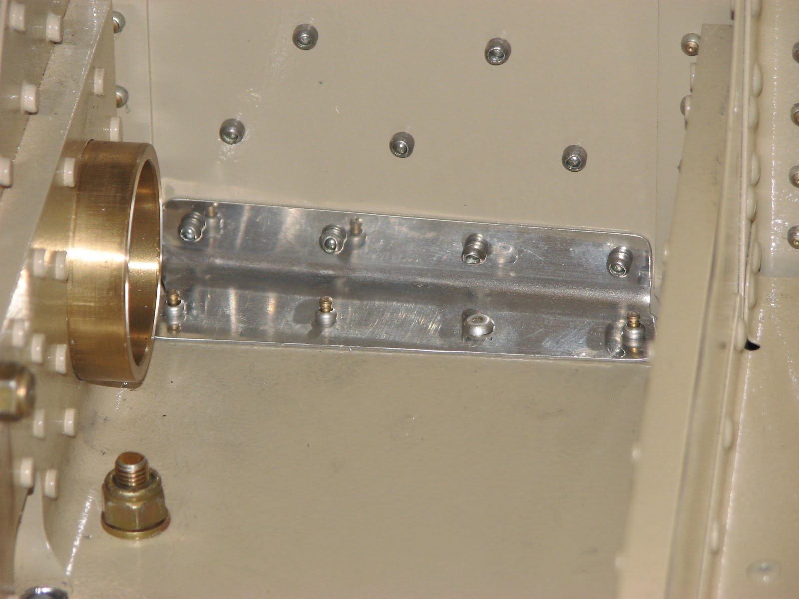
The next one shows the not so pretty left side. The outer rivets are pulled short but the aft one had a drill bit broken off in it when I tried to remove it. I decided to just add an additional hole and set an additional rivet instead of removing these. The access is really nasty and I did not want to break off another drill bit.

There was still one rivet in those added holes that did not set right and I replaced the rivet today. I did the very same thing as the first time and this time it pulled just fine.
By the way, I found so far that the best way of removing one of the these CherryMax® rivets is to do just like with ordinary rivets. Drill off the head, either with a bare drill bit or with one of the rivet removers that align the bit by using the circumference of the head. Once the head's removed, use a steel punch and a hammer and drive the stem out. That went very well for me but the rivets were obviously not really set, so keep that in mind.
After the rivet replacements I got to install the right leg and put all the nuts and bolts back in place.

This also provided for a nice angle shot at the AN5 bolts on the right side that shows very nicely how the longer bolts are perfect.

Then everything was torqued to specs but not yet marked with torque seal as I will re-torque everything right before the inspection and then seal it.

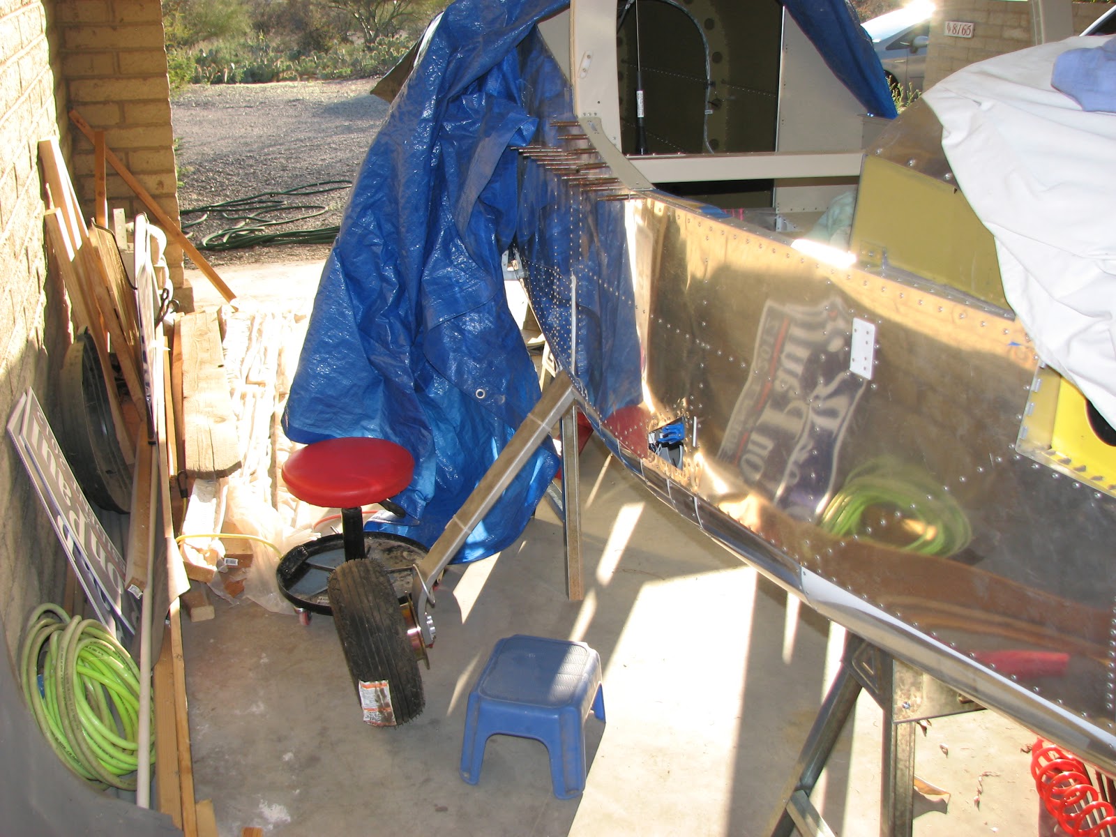
The last step was to get the plane off the sawhorses with the help of my wife.

Finally, after 34.5 hours, the legs are back on and the plane is off the sawhorses. I'm not completely done with the SB though. I still need to clean up the interior, remove some debris in hard to reach places and reinstall the ELT before I can tick this SB off.
Monday, March 4, 2013
AN5 bolts too short
Tonight I had a chance to find out if my concerns about the length of the AN5 bolts I expressed yesterday were true. I really hate it when I'm right about stuff like that. They sure are too short to show at least one thread through the nut when using two AN960-516 washers and I sure won't leave out a washer just because Van's was too cheap to provide thinner ones.
I've just ordered a few AN960-516L as well as 4 AN5-23A bolts. I think I might just insert the slightly longer bolts instead of using the thinner washers. I would have to replace both washers to allow for enough grip on the nuts and therefore I have to remove the bolts anyway.
Let's hope the hardware makes it here until Wednesday evening when I have time to build again.
I've just ordered a few AN960-516L as well as 4 AN5-23A bolts. I think I might just insert the slightly longer bolts instead of using the thinner washers. I would have to replace both washers to allow for enough grip on the nuts and therefore I have to remove the bolts anyway.
Let's hope the hardware makes it here until Wednesday evening when I have time to build again.
Sunday, March 3, 2013
Left Leg Attached - Again!
Putting it all back together was much harder than I thought. Or I might have just forgotten how awkward it was the first time around. Working on this alone is not optimal although I wouldn't know how much easier it would be to have a second pair of hands around. Before a leg could get remounted to the fuselage I had to install the beefed up wear plates to the bottom of the U-section. Torquing those screws was a bit tricky but with a whole set of adapters and gender changers the job could finally get done.


Notice that I had a pair of AN5 bolts inserted to help aligning the plates correctly. Here you get a view from the bottom:


Now attaching the left leg was a real hassle. With a lot of wiggling the brackets and leg finally got aligned to get the bolts in the corresponding holes I could at least put the nuts on all the bolts. Didn't torque anything yet nor get the nuts tight.

It got too late to finish the job, but at least I know that the work sessions can be short enough to fit into the evenings this week.
I almost forgot, I have one concern about the hardware provided by Van's. The plans show that there's a washer underneath the nuts and the bolt heads for the outboard bracket. They ask for AN960-516 and one for AN960-516L. Well, the plans do that with the fancy NAS1149 number that I cannot recall right now. However, the -516L washers are not provided (and not listed in the inventory) nor are there any leftovers from the rest of the kit hardware. The plans also don't show where the -516L goes or where the thick one should go. Even worse, it looks like the AN5 bolts might not be long enough to get sufficiently through the stop nuts using two -516 washers. We will see if this is a real problem when I tighten the bolts.


Notice that I had a pair of AN5 bolts inserted to help aligning the plates correctly. Here you get a view from the bottom:


Now attaching the left leg was a real hassle. With a lot of wiggling the brackets and leg finally got aligned to get the bolts in the corresponding holes I could at least put the nuts on all the bolts. Didn't torque anything yet nor get the nuts tight.

It got too late to finish the job, but at least I know that the work sessions can be short enough to fit into the evenings this week.
I almost forgot, I have one concern about the hardware provided by Van's. The plans show that there's a washer underneath the nuts and the bolt heads for the outboard bracket. They ask for AN960-516 and one for AN960-516L. Well, the plans do that with the fancy NAS1149 number that I cannot recall right now. However, the -516L washers are not provided (and not listed in the inventory) nor are there any leftovers from the rest of the kit hardware. The plans also don't show where the -516L goes or where the thick one should go. Even worse, it looks like the AN5 bolts might not be long enough to get sufficiently through the stop nuts using two -516 washers. We will see if this is a real problem when I tighten the bolts.
Wednesday, February 27, 2013
Wear Plates Primed
Not much to report from tonight's session. As planned, I prepped and primed the wear plates and the associated aluminum buffers.

The following reassembly of the gear legs might have to wait till the weekend.

The following reassembly of the gear legs might have to wait till the weekend.
Tuesday, February 26, 2013
Wear Plates Countersunk
It is a long time since I last had a job that I could do in my shop and tonight I could do one again. The steel wear plates had to be countersunk (on their bottom side!). A few weeks ago I had already ordered the 1/2" die with a 1/4" pilot and I could finally put it to use.

This was after the first one was done.

And here the set is complete. The nice thing about countersinking steel is that you can hardly go too deep by accident.
It was already dark when I was done and so I planned to prime the aluminum and steel parts tomorrow after work.

This was after the first one was done.

And here the set is complete. The nice thing about countersinking steel is that you can hardly go too deep by accident.
It was already dark when I was done and so I planned to prime the aluminum and steel parts tomorrow after work.
Monday, February 25, 2013
6" Drill Bits Arrived
The 6" drill bits from Avery Tools arrived today and I got right to work on the plane when I came home from the paying job and found the parcel.

The reflection of the drill bit on the template surface really helped getting the holes drilled straight. However, I cannot understand why Van's was so cheap to just provide one template for two sides. I ended up having remove those nuts holding the template over and over to swap the template from one side to the other and then back again for drilling the 1/4" holes. Come on, really, Van's?

Here you see the right side after opening up the pre-drilled holes to 1/4". After that the template has to get switched back to the left side as you need the reflection to ensure a perpendicular drill bit.
 Finally, the chips were removed and the two mount assemblies were removed from the plane, while making sure that they stayed aligned as they were drilled to get marked clearly for reassembly. Also, I deburred the freshly drilled holes. The drill bits are really high quality and there were hardly any noticeable burrs to remove.

The sun had set by then and I called it a day after another 1.5 hours. So far, I have spent 25 hours working on this SB.

The reflection of the drill bit on the template surface really helped getting the holes drilled straight. However, I cannot understand why Van's was so cheap to just provide one template for two sides. I ended up having remove those nuts holding the template over and over to swap the template from one side to the other and then back again for drilling the 1/4" holes. Come on, really, Van's?

Here you see the right side after opening up the pre-drilled holes to 1/4". After that the template has to get switched back to the left side as you need the reflection to ensure a perpendicular drill bit.
 Finally, the chips were removed and the two mount assemblies were removed from the plane, while making sure that they stayed aligned as they were drilled to get marked clearly for reassembly. Also, I deburred the freshly drilled holes. The drill bits are really high quality and there were hardly any noticeable burrs to remove.
The sun had set by then and I called it a day after another 1.5 hours. So far, I have spent 25 hours working on this SB.
Tuesday, February 19, 2013
6" #30 Drill Bit Needed
I am glad that I got to work on the plane to night, as this could possibly safe me some valuable time waiting for new tools to arrive. I put together the new set of bolts, brackets and wear plates on the left side, to see how accessible the template and its holes would be for match-drilling. As it is imperative that the drill bit would be aligned perpendicular during the drill process to ensure a straight hole for the bolts, I also wanted to see how well the reflection of the drill bit on the template could be used to ensure that.
Putting the assembly together was the easy part, although it could help to have a second pair of hands for this.


It turned out that none of my drill bits would actually get the job done. The problem is that a 12" long drill bit is almost touching the back rest and wouldn't allow to attach a drill to it. And the short jobber bit wouldn't work because the chuck of the drill would be interfering with the side of the U-section. I measured and calculated and came up with a 6" bit to be perfect. I ordered one in #30 and one in 1/4", so opening up the match-drilled #30 hole would not get further delayed. I could probably get a usable 1/4" bit from a hardware store (or I might even have one in my toolbox ) but the shipping for just one drill bit is more than 200% of the bit's value and so I just added another one to it.
I hope the bits arrive before the weekend...
Putting the assembly together was the easy part, although it could help to have a second pair of hands for this.


It turned out that none of my drill bits would actually get the job done. The problem is that a 12" long drill bit is almost touching the back rest and wouldn't allow to attach a drill to it. And the short jobber bit wouldn't work because the chuck of the drill would be interfering with the side of the U-section. I measured and calculated and came up with a 6" bit to be perfect. I ordered one in #30 and one in 1/4", so opening up the match-drilled #30 hole would not get further delayed. I could probably get a usable 1/4" bit from a hardware store (or I might even have one in my toolbox ) but the shipping for just one drill bit is more than 200% of the bit's value and so I just added another one to it.
I hope the bits arrive before the weekend...
Monday, February 18, 2013
Doublers Riveted
Today was the second attempt at dealing with the CherryMax® rivets. This turned out to be not all so bad as yesterday. I started with riveting the 1202-T and -U angles to the U-section. This time I started the outer rivets from the belly side. As you can see, they were properly pulled this time.

Access with the manual riveter to the front rivet was easy but the aft one was a real challenge. I needed all the wiggle room I could get and had to cant the rivet stem when extending the riveter's arm to get a grip for the next pull.

A riveter with a much longer head would be desirable for this job. The rest of the job was quite uneventful and business as usual. Here's a shot from half time riveting the doublers to the right side skin.

And shortly thereafter the riveting part of the job was done.

With a coarse grinding wheel I beveled the edges of the landing gear attach brackets.

Here you see both finished brackets among some workbench clutter.

The next step is to match drill additional holes into the U-section for additional bolts to be added to hold the gear legs. This is a job where I will just get one try, hit or miss, so I decided to postpone that work to a day when I'm fresh.
So far I've spent 22.5 hours on the SB.

Access with the manual riveter to the front rivet was easy but the aft one was a real challenge. I needed all the wiggle room I could get and had to cant the rivet stem when extending the riveter's arm to get a grip for the next pull.

A riveter with a much longer head would be desirable for this job. The rest of the job was quite uneventful and business as usual. Here's a shot from half time riveting the doublers to the right side skin.

And shortly thereafter the riveting part of the job was done.

With a coarse grinding wheel I beveled the edges of the landing gear attach brackets.

Here you see both finished brackets among some workbench clutter.

The next step is to match drill additional holes into the U-section for additional bolts to be added to hold the gear legs. This is a job where I will just get one try, hit or miss, so I decided to postpone that work to a day when I'm fresh.
So far I've spent 22.5 hours on the SB.
Sunday, February 17, 2013
Beware of the CherryMax®!
CherryMax® rivets that is. This pull-style rivet looks so familiar but behaves to differently and is very unforgiving - but I'll get to that in a moment.
I had worked on the SB during the week as much as I could (which wasn't all that much, but at least I worked on it). So, I had done all the deburring of the side skin doubler and the newly drilled holes. I've also managed to prime the doublers on one side. When I removed the vinyl on one of the large doublers, I've noticed that it some light corrosion which I also removed and sprayed over with primer. That should last until the plane gets painted.
When I sprayed the primer it was already dark and pretty cold too, so I used two halogen lamps to heat up the metal and expedite the curing process. That where the yellowish tint in the following picture is coming from.

Yesterday then was the big work day where I had planned to put all the doublers in place and rivet them on. First I cleaned the U-Section to put the now two skin attach angles in place, using these fancy CherryMax® rivets.

I tapped the wing bolt bushing out a bit more to see how I could get access to the rivet for riveting. I chose the forward-most position as an example as this one appeared to be the trickiest one to get to.

You can see the stripped down riveter in the upper right side of the picture. It appeared that it was a close call but possible to get to the rivet and pull it straight. As a spoiler, and to avoid that you're making the same mistake, let me tell you right here, that it was not good enough. And that includes the aft=most position as well. Do not follow my example and rivet those from below.
The angle was put in place, clecoed and rivets where inserted.

Now, to my own defense, I have to say that I did indeed read the notes about how to install CherryMax® rivets and how important it was that the stem was not tilted while pulling. I can just guess that pulling 20,000 LP4-3 rivets that don't give a damn about the angle of pull, might have given me a callous attitude towards sensing such a tilt.
To me the access to the rivet appeared to be perfectly ok and so I riveted the angles in place

Pulling these rivets feels different than LP4-3, so I didn't know what to make of the sensations I felt in my hand and the unusual sounds I heard. First I thought, it was much easier than I thought it would be and then I looked at the heads. If you look closely, you can see that the stem left a hole in the head on the foremost rivet. The center two do not show that hole. An inspection from below confirmed my fears:
 .
.
The stems of the aft and front rivets had not pulled in sufficiently and the stem broke prematurely! I decided to try to drill out the rivets, following Van's note about CherryMax® rivets. While drilling into the stem of the first rivet using a #40 angle drill bit, something felt odd and I pulled the drill out. Oh no!

The drill bit had broken off inside the stem and the piece was stuck in the head. There was no way for me to remove the rivet now, without causing serious damage to this delicate area. I decided against further experiments and instead chose to add two more holes to the angles and the U-section. (I might decide to use a rivet gun on the two stems that have not seated properly to improve the rivet strength but I first have to get one.)

Now being away from the sides of the U-section, the access was definitely easier and the riveter worked as it should.

The rest of this ordeal went much smoother after this CherryMax® rivet episode. The usual CS4-4 and LP4-3 were no problem at all, also the ChreeyMax out the skins were no issue as they were all easily accessible.


That concluded Saturday's work.
Sunday started with the removal of the 1202T angle in the U-section on the right side. This one was much tougher as the ELT bracket is very much in the way of any operation you would like to perform in this area.
The angle drill and thanks to some Yoga lessons helped in getting the job done right.

With the experience from the left side, drilling out those rivets on the right side was a quick job. Note that I clecoed the skin while removing rivets to give it a bit of support.

Match-drilling and deburring went along and soon the skin was ready to receive the doublers.

The doublers were scuffed and primed and dried in the warm sun (76 degF today!).

Right at sunset I finished clecoing the doublers in place for the riveting action to come.

I had worked on the SB during the week as much as I could (which wasn't all that much, but at least I worked on it). So, I had done all the deburring of the side skin doubler and the newly drilled holes. I've also managed to prime the doublers on one side. When I removed the vinyl on one of the large doublers, I've noticed that it some light corrosion which I also removed and sprayed over with primer. That should last until the plane gets painted.
When I sprayed the primer it was already dark and pretty cold too, so I used two halogen lamps to heat up the metal and expedite the curing process. That where the yellowish tint in the following picture is coming from.

Yesterday then was the big work day where I had planned to put all the doublers in place and rivet them on. First I cleaned the U-Section to put the now two skin attach angles in place, using these fancy CherryMax® rivets.

I tapped the wing bolt bushing out a bit more to see how I could get access to the rivet for riveting. I chose the forward-most position as an example as this one appeared to be the trickiest one to get to.

You can see the stripped down riveter in the upper right side of the picture. It appeared that it was a close call but possible to get to the rivet and pull it straight. As a spoiler, and to avoid that you're making the same mistake, let me tell you right here, that it was not good enough. And that includes the aft=most position as well. Do not follow my example and rivet those from below.
The angle was put in place, clecoed and rivets where inserted.

Now, to my own defense, I have to say that I did indeed read the notes about how to install CherryMax® rivets and how important it was that the stem was not tilted while pulling. I can just guess that pulling 20,000 LP4-3 rivets that don't give a damn about the angle of pull, might have given me a callous attitude towards sensing such a tilt.
To me the access to the rivet appeared to be perfectly ok and so I riveted the angles in place

Pulling these rivets feels different than LP4-3, so I didn't know what to make of the sensations I felt in my hand and the unusual sounds I heard. First I thought, it was much easier than I thought it would be and then I looked at the heads. If you look closely, you can see that the stem left a hole in the head on the foremost rivet. The center two do not show that hole. An inspection from below confirmed my fears:
 .
.The stems of the aft and front rivets had not pulled in sufficiently and the stem broke prematurely! I decided to try to drill out the rivets, following Van's note about CherryMax® rivets. While drilling into the stem of the first rivet using a #40 angle drill bit, something felt odd and I pulled the drill out. Oh no!

The drill bit had broken off inside the stem and the piece was stuck in the head. There was no way for me to remove the rivet now, without causing serious damage to this delicate area. I decided against further experiments and instead chose to add two more holes to the angles and the U-section. (I might decide to use a rivet gun on the two stems that have not seated properly to improve the rivet strength but I first have to get one.)

Now being away from the sides of the U-section, the access was definitely easier and the riveter worked as it should.

The rest of this ordeal went much smoother after this CherryMax® rivet episode. The usual CS4-4 and LP4-3 were no problem at all, also the ChreeyMax out the skins were no issue as they were all easily accessible.


That concluded Saturday's work.
Sunday started with the removal of the 1202T angle in the U-section on the right side. This one was much tougher as the ELT bracket is very much in the way of any operation you would like to perform in this area.
The angle drill and thanks to some Yoga lessons helped in getting the job done right.

With the experience from the left side, drilling out those rivets on the right side was a quick job. Note that I clecoed the skin while removing rivets to give it a bit of support.

Match-drilling and deburring went along and soon the skin was ready to receive the doublers.

The doublers were scuffed and primed and dried in the warm sun (76 degF today!).

Right at sunset I finished clecoing the doublers in place for the riveting action to come.

Sunday, February 10, 2013
Landing Gear is Off
My shop day started chilly temps down in the lower 40s and I decided to utilize the propane heater for my second day working on the Landing Gear SB. Thanks to calm to no wind conditions, the heater worked pretty well in the open car port. In just 45 minutes the first leg was off.
 The only part of the landing gear that remains inside the tunnel, is the inboard mounting block that also connects to the brake line. I put a paper towel under the brake line fitting, to catch any drops of brake fluid coming out of it.
 The right leg was up for removal next.
 This one gave me some grief as the outboard mounting block could not get removed without drilling out the infamous rivet again that keeps that block from easily sliding in and out the tunnel. Eventually, after 45 minutes again, the leg was removed and stored.
 The part in the instructions about what parts of the removed landing gear hardware we are supposed to retain was text only and, me being a visual person, I needed a while to look up the drawings in the landing gear section to identify what they were. As a short-cut here is a picture of the hardware for one side.
 It consists of the two nuts of the outboard bolts (the washers were not mentioned, but I wonder why, so I threw them in anyway), the outboard mounting bracket and the inboard wear plate.
A closer look at the washers showed some odd deformation on two of them. You can see it best on the washer in the center of the following picture.
 This indicates some very small stress points and I cannot figure where this was coming from. This landing gear wasn't even in use yet, so I can really see how this could cause some stress related fatigue and failure on the U-section where this washer was located.
Next step was to mark the side skins to highlight the region where rivets had to be removed.

 I drilled out all the rivets inside the marked area on the left side. And pushed out any stubborn stems that didn't want to just fall out. The 4 rivets in the U-Section that attach the stiffener for the side skin were most awkward to get to. The recommended 12x#30 drill bit is way too long to get to them and the jobber bit is too short. I ended up using my rivet remover kit that is about 6" long. This will be even trickier on the right side as the ELT bracket will prevent me from using even that 6" long bit. I anticipate hacing to use the angle drill there but I haven't tried yet.
 Then the doublers were deburred and clecoed onto the side skins. Some 50 something holes of drilling later, the side skin was perforated as requested and it looked like a cleco hedgehog.
 Before I removed these doublers, I match-drilled the new 1202U side skin stiffener which will go on the upper side of the U-Section (in addition to 1202T, the one on the lower side). This stiffener combo is a bit weird as the SB kit comes with a replacement 1202T that looks pretty much like the 1202T that I just removed from the plane. I cannot see that the material of the new 1202T was any thicker or different from the old one.
 I assume we will be asked to discard the old one and I will surely install the new 1202T, I just would like to understand what the difference is.
Next, all the doublers and clecos came off again and the holes and parts were deburred. They are ready for riveting now and I think I'll prime them before that. These doublers will be in an area where they could easily collect moisture and grow corrosion without noticing.
This was the time when daylight was getting scarce and I called it a day. I'm now 9 hours into the SB and close to halfway done with it.
During the week I plan to throw some hours in for prep work. I need to prep the doublers for priming and prime them, and I think U should be able to do some of the drilling out of rivets during one evening as well.


A closer look at the washers showed some odd deformation on two of them. You can see it best on the washer in the center of the following picture.

Next step was to mark the side skins to highlight the region where rivets had to be removed.


Next, all the doublers and clecos came off again and the holes and parts were deburred. They are ready for riveting now and I think I'll prime them before that. These doublers will be in an area where they could easily collect moisture and grow corrosion without noticing.
This was the time when daylight was getting scarce and I called it a day. I'm now 9 hours into the SB and close to halfway done with it.
During the week I plan to throw some hours in for prep work. I need to prep the doublers for priming and prime them, and I think U should be able to do some of the drilling out of rivets during one evening as well.
Subscribe to:
Posts (Atom)


