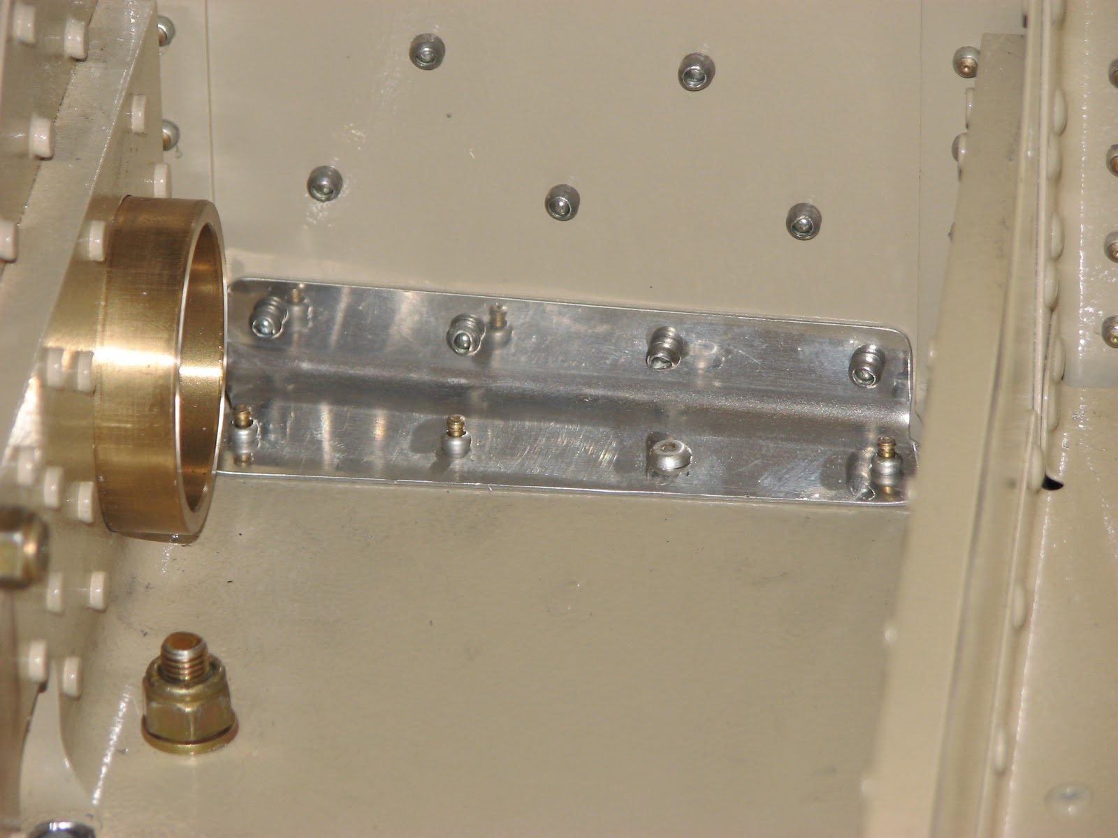
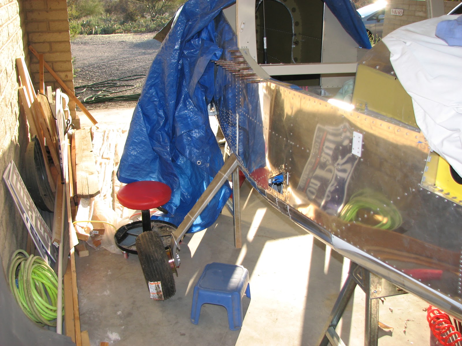
I was mainly closing out sections tonight. One of them was the landing gear section. The little covers I had primed yesterday were ready to get riveted.
So on they went.
And just as quickly they were riveted on.
I also finalized the wiring on the Avionics by tightening and cutting the wire ties.
Adjusting the audio levels is probably only doable in the hangar when everything is hooked up, including the mechanical stall warner.
I also crept forward in the Miscellaneous section by starting to install the retention devices.
And then the mosquitos got a bit annoying as it was dark and me the only lighted food source around.
Showing posts with label Main Gear. Show all posts
Wednesday, August 21, 2013
Tuesday, April 2, 2013
Brake System Bled
I managed to flush the brake system once again over the weekend. Hopefully, we removed all the air now and the system will stay leak-free.


Speaking of leak-free, I tried the brakes with my feet while sitting in the plane, to make sure that they felt air-free and gave a good, hard response. This is what triggered the leaks last time around.

So, after this was all done and I was about to cover up the plane for the night, I checked the fittings for leakage by touching them with a paper towel. On the right side, on the lower fittings for the left and the right pedal, I got a minimal response. The response was so little that I cannot say, if this was brake fluid or something else or if it was some fluid that might have been on the tips of the pressure lines and got wiped onto the fitting when hooking up the lines.
I put some newspaper sheets below the pedals again and will check in a few days what happened. If it is a minor seepage on the right side, I would leave it alone and fix it with the annual - once it is registered.
Speaking of leak-free, I tried the brakes with my feet while sitting in the plane, to make sure that they felt air-free and gave a good, hard response. This is what triggered the leaks last time around.
So, after this was all done and I was about to cover up the plane for the night, I checked the fittings for leakage by touching them with a paper towel. On the right side, on the lower fittings for the left and the right pedal, I got a minimal response. The response was so little that I cannot say, if this was brake fluid or something else or if it was some fluid that might have been on the tips of the pressure lines and got wiped onto the fitting when hooking up the lines.
I put some newspaper sheets below the pedals again and will check in a few days what happened. If it is a minor seepage on the right side, I would leave it alone and fix it with the annual - once it is registered.
Wednesday, March 27, 2013
Brake System Filled
I threw in a short work session when I got home, so I could determine if the brake system is now leak free. As I mentioned before, it might take a few days before the leaks show, so I wanted to fill the system as early as possible.
My wife was not available, so I could not bleed the system as I had previously done - pumping fluid while a second pair of hands is vigorously moving the pedals back and forth. That way I got the last bubbles out of the brake cylinders where they love to hide.


You can see about 1.5" inches of air slowly moving backwards (well, no, you can't SEE the movement, you'll have to take my word for it) in the lines for the left brake. I expect the same to happen on the right side when it had some time to settle. I filled the right side last and it usually takes some 10 minutes before the air is creeping back.
For filling I used the trusted setup from last time.


Having a bit of experience with this now, I did not waste a lot of fluid like I did last time. Not that it would be important as the quart is way too much for filling the system - even with extended bleeding.
I hope I can wash the last bit of air out on Friday evening. By then I might also have a first result on the leak test.
My wife was not available, so I could not bleed the system as I had previously done - pumping fluid while a second pair of hands is vigorously moving the pedals back and forth. That way I got the last bubbles out of the brake cylinders where they love to hide.
You can see about 1.5" inches of air slowly moving backwards (well, no, you can't SEE the movement, you'll have to take my word for it) in the lines for the left brake. I expect the same to happen on the right side when it had some time to settle. I filled the right side last and it usually takes some 10 minutes before the air is creeping back.
For filling I used the trusted setup from last time.
Having a bit of experience with this now, I did not waste a lot of fluid like I did last time. Not that it would be important as the quart is way too much for filling the system - even with extended bleeding.
I hope I can wash the last bit of air out on Friday evening. By then I might also have a first result on the leak test.
Monday, March 25, 2013
Pedals Re-Installed
After coming home from work I felt like cleaning up the left-overs from yesterday. The pedals had to go back in and it felt like a good task to do for an evening worth of work. I had never done it the "right" way, while the fuselage was on its belly, so it was a learning curve for me to overcome. It turned out that it was easier than putting them in while the fuse was on its side.

Here the left and the middle upper blocks go in with the left pedals. This is just to get the thing set up and stabilized. It has to come half-way out again to insert the right pedals in the bearing blocks - which you see in the following picture.

Fiddling with the lower blocks and the bolts was a job where I wished I could be hanging upside down from the ceiling as access would have been much easier. My calves and back muscles will certainly be sore tomorrow.
Notice the helpful bungee cord to position the pedals in their aft-most position. Really handy when you don't have access to a second pair of hands.

The final step was to re-attach the hydraulic lines - mainly to cover up the holes Arizonan insects love to nest in. I was tired at that point and just hand tightened them. I also re-attached the rudder cables which simple, except for inserting the cotter pins. You just need two hands for that job and getting two arms under the instrument panel while being half-way outside the airplane is not really easy to do.
This repair, which I'm not certain is complete yet, has taken me 5.5 hours so far. Not bad at all; I really don't understand why I was dreading it so much. I guess, it was more a psychological block than being put off by the time it would take.

Now, I have to tighten those line fittings and then do some magic with cable ties that I had to cut in order to remove the pedals. That should not take too long and then I'm off to bleeding the brakes again and see if this all was worth the effort.
After considering the next steps on my day off (from the shop), I decided to leave the cable ties where they are - in the bag - at least for now. I will tighten the line fittings and then go straight to filling the system with brake fluid and bleeding. That way, I can see if this effort fixed the problem before I put obstacles in the way again.
Actually, it might take a few days for the leaks to show if there are any. I remember that last time when that happened, it first appeared to be dry and it was only after a few days when the leaks showed.
Here the left and the middle upper blocks go in with the left pedals. This is just to get the thing set up and stabilized. It has to come half-way out again to insert the right pedals in the bearing blocks - which you see in the following picture.
Fiddling with the lower blocks and the bolts was a job where I wished I could be hanging upside down from the ceiling as access would have been much easier. My calves and back muscles will certainly be sore tomorrow.
Notice the helpful bungee cord to position the pedals in their aft-most position. Really handy when you don't have access to a second pair of hands.
The final step was to re-attach the hydraulic lines - mainly to cover up the holes Arizonan insects love to nest in. I was tired at that point and just hand tightened them. I also re-attached the rudder cables which simple, except for inserting the cotter pins. You just need two hands for that job and getting two arms under the instrument panel while being half-way outside the airplane is not really easy to do.
This repair, which I'm not certain is complete yet, has taken me 5.5 hours so far. Not bad at all; I really don't understand why I was dreading it so much. I guess, it was more a psychological block than being put off by the time it would take.
Now, I have to tighten those line fittings and then do some magic with cable ties that I had to cut in order to remove the pedals. That should not take too long and then I'm off to bleeding the brakes again and see if this all was worth the effort.
After considering the next steps on my day off (from the shop), I decided to leave the cable ties where they are - in the bag - at least for now. I will tighten the line fittings and then go straight to filling the system with brake fluid and bleeding. That way, I can see if this effort fixed the problem before I put obstacles in the way again.
Actually, it might take a few days for the leaks to show if there are any. I remember that last time when that happened, it first appeared to be dry and it was only after a few days when the leaks showed.
Sunday, March 24, 2013
Fittings Re-Fitted
After finishing the MLG SB, I had to do one extra thing before being able to refill the brake system with fluid. That one thing was to remove the pedals from the plane, remove the fittings and clean them and re-fit them to the brake cylinders - this time with Bakerseal as sealant.

I was able to remove the pedals with just removing the bearing blocks and not removing the little metal shield that holds the wires off the pedals. That earned me a deep scratch in the powder coating, that I patched up with primer. I will have to protect this and be extra careful when reinserting them into place.
Other than that the pedals came out easier than I had expected. Once they were removed I started on removing the fittings and cleaning the threads from the previously used sealant.
The black rings around the fittings shows the old sealant still in place.

I cleaned the fittings by repeatedly submerging them in MEK and then rubbing off the sealant with a rag and also brushing the threads with a brass brush. Then I dried the fittings inside out, and particularly the threads, with compressed air before applying a thin coat of Bakerseal and reinserting them.
When reinserting, I tightened them with a standard length 3/8" wrench until I felt a strong resistance. Then I used the adjustable wrench of 8" length to turn it at least one more turn until I felt a very strong resistance and got the feeling that I might get stuck going another full turn.


The 45 degree fittings went in much deeper than the 90 degree ones. All in all, the 45 degree fittings were turnable until only one thread showed, while the 90 degree ones show 4 threads.


Comparing this seating depth with what I saw on Dave's blog, I should be save to put them back into the plane now. I certainly do not want to remove them again!
I was able to remove the pedals with just removing the bearing blocks and not removing the little metal shield that holds the wires off the pedals. That earned me a deep scratch in the powder coating, that I patched up with primer. I will have to protect this and be extra careful when reinserting them into place.
Other than that the pedals came out easier than I had expected. Once they were removed I started on removing the fittings and cleaning the threads from the previously used sealant.
The black rings around the fittings shows the old sealant still in place.
I cleaned the fittings by repeatedly submerging them in MEK and then rubbing off the sealant with a rag and also brushing the threads with a brass brush. Then I dried the fittings inside out, and particularly the threads, with compressed air before applying a thin coat of Bakerseal and reinserting them.
When reinserting, I tightened them with a standard length 3/8" wrench until I felt a strong resistance. Then I used the adjustable wrench of 8" length to turn it at least one more turn until I felt a very strong resistance and got the feeling that I might get stuck going another full turn.
The 45 degree fittings went in much deeper than the 90 degree ones. All in all, the 45 degree fittings were turnable until only one thread showed, while the 90 degree ones show 4 threads.
Comparing this seating depth with what I saw on Dave's blog, I should be save to put them back into the plane now. I certainly do not want to remove them again!
Monday, March 18, 2013
Removing the Pedals
So, it turned out that I actually had completed the SB without even realizing. There were so many steps left on my work sheet but after a closer look they revealed to be applicable only to flying or completed RV-12s.
The only thing for me left to do (at this point) was to re-install the ELT and I decided to hold off on that for just a little while as the next steps might cause some bumps to the fuselage that could trigger the ELT if it was real sensitive.
These next steps are the removal of the pedals that I dreaded for so long. I started by removing the little aluminum angles that are screwed onto the tunnel structure and the panel that would prevent me from pulling out the pedals to the aft. Working in this area is really no fun at all as access is almost impossible without lieing upside down with the head under the panel. I am trying to get around this if I can. I did not have much time yet to remove all the bolts and screws holding the pedals yet, so I leave this post as a stub until I finished the task.
I removed those angles though and have free access to remove the pedals now.
The only thing for me left to do (at this point) was to re-install the ELT and I decided to hold off on that for just a little while as the next steps might cause some bumps to the fuselage that could trigger the ELT if it was real sensitive.
These next steps are the removal of the pedals that I dreaded for so long. I started by removing the little aluminum angles that are screwed onto the tunnel structure and the panel that would prevent me from pulling out the pedals to the aft. Working in this area is really no fun at all as access is almost impossible without lieing upside down with the head under the panel. I am trying to get around this if I can. I did not have much time yet to remove all the bolts and screws holding the pedals yet, so I leave this post as a stub until I finished the task.
I removed those angles though and have free access to remove the pedals now.
Saturday, March 16, 2013
Legs Back On
The longer bolts had arrived more than a week ago but other things kept me from getting back to work.
I didn't do more during the past week than checking that the length of the AN5-23A bolts were really the right ones. And they were.
Today, I got around to putting all back together. One leg was already on but needed some wiggling and adjusting and torquing to finish the job and the right side needed the whole installation done.


These are the longer AN5 bolts and you can see that they are just the right size. The shorter -22As were not getting through the lock feature of the nuts unless they'd be torqued to final specs and how could you measure the friction torque that way?
I also drilled out some of the CherryMax® rivets I had found earlier. Here's one picture showing the fixed up right side after replacing one rivet. It's the second from the left and I pulled it from below as you can see.

The next one shows the not so pretty left side. The outer rivets are pulled short but the aft one had a drill bit broken off in it when I tried to remove it. I decided to just add an additional hole and set an additional rivet instead of removing these. The access is really nasty and I did not want to break off another drill bit.

There was still one rivet in those added holes that did not set right and I replaced the rivet today. I did the very same thing as the first time and this time it pulled just fine.
By the way, I found so far that the best way of removing one of the these CherryMax® rivets is to do just like with ordinary rivets. Drill off the head, either with a bare drill bit or with one of the rivet removers that align the bit by using the circumference of the head. Once the head's removed, use a steel punch and a hammer and drive the stem out. That went very well for me but the rivets were obviously not really set, so keep that in mind.
After the rivet replacements I got to install the right leg and put all the nuts and bolts back in place.

This also provided for a nice angle shot at the AN5 bolts on the right side that shows very nicely how the longer bolts are perfect.

Then everything was torqued to specs but not yet marked with torque seal as I will re-torque everything right before the inspection and then seal it.


The last step was to get the plane off the sawhorses with the help of my wife.

Finally, after 34.5 hours, the legs are back on and the plane is off the sawhorses. I'm not completely done with the SB though. I still need to clean up the interior, remove some debris in hard to reach places and reinstall the ELT before I can tick this SB off.
I didn't do more during the past week than checking that the length of the AN5-23A bolts were really the right ones. And they were.
Today, I got around to putting all back together. One leg was already on but needed some wiggling and adjusting and torquing to finish the job and the right side needed the whole installation done.
These are the longer AN5 bolts and you can see that they are just the right size. The shorter -22As were not getting through the lock feature of the nuts unless they'd be torqued to final specs and how could you measure the friction torque that way?
I also drilled out some of the CherryMax® rivets I had found earlier. Here's one picture showing the fixed up right side after replacing one rivet. It's the second from the left and I pulled it from below as you can see.
The next one shows the not so pretty left side. The outer rivets are pulled short but the aft one had a drill bit broken off in it when I tried to remove it. I decided to just add an additional hole and set an additional rivet instead of removing these. The access is really nasty and I did not want to break off another drill bit.
There was still one rivet in those added holes that did not set right and I replaced the rivet today. I did the very same thing as the first time and this time it pulled just fine.
By the way, I found so far that the best way of removing one of the these CherryMax® rivets is to do just like with ordinary rivets. Drill off the head, either with a bare drill bit or with one of the rivet removers that align the bit by using the circumference of the head. Once the head's removed, use a steel punch and a hammer and drive the stem out. That went very well for me but the rivets were obviously not really set, so keep that in mind.
After the rivet replacements I got to install the right leg and put all the nuts and bolts back in place.
This also provided for a nice angle shot at the AN5 bolts on the right side that shows very nicely how the longer bolts are perfect.
Then everything was torqued to specs but not yet marked with torque seal as I will re-torque everything right before the inspection and then seal it.
The last step was to get the plane off the sawhorses with the help of my wife.
Finally, after 34.5 hours, the legs are back on and the plane is off the sawhorses. I'm not completely done with the SB though. I still need to clean up the interior, remove some debris in hard to reach places and reinstall the ELT before I can tick this SB off.
Monday, March 4, 2013
AN5 bolts too short
Tonight I had a chance to find out if my concerns about the length of the AN5 bolts I expressed yesterday were true. I really hate it when I'm right about stuff like that. They sure are too short to show at least one thread through the nut when using two AN960-516 washers and I sure won't leave out a washer just because Van's was too cheap to provide thinner ones.
I've just ordered a few AN960-516L as well as 4 AN5-23A bolts. I think I might just insert the slightly longer bolts instead of using the thinner washers. I would have to replace both washers to allow for enough grip on the nuts and therefore I have to remove the bolts anyway.
Let's hope the hardware makes it here until Wednesday evening when I have time to build again.
I've just ordered a few AN960-516L as well as 4 AN5-23A bolts. I think I might just insert the slightly longer bolts instead of using the thinner washers. I would have to replace both washers to allow for enough grip on the nuts and therefore I have to remove the bolts anyway.
Let's hope the hardware makes it here until Wednesday evening when I have time to build again.
Sunday, March 3, 2013
Left Leg Attached - Again!
Putting it all back together was much harder than I thought. Or I might have just forgotten how awkward it was the first time around. Working on this alone is not optimal although I wouldn't know how much easier it would be to have a second pair of hands around. Before a leg could get remounted to the fuselage I had to install the beefed up wear plates to the bottom of the U-section. Torquing those screws was a bit tricky but with a whole set of adapters and gender changers the job could finally get done.


Notice that I had a pair of AN5 bolts inserted to help aligning the plates correctly. Here you get a view from the bottom:


Now attaching the left leg was a real hassle. With a lot of wiggling the brackets and leg finally got aligned to get the bolts in the corresponding holes I could at least put the nuts on all the bolts. Didn't torque anything yet nor get the nuts tight.

It got too late to finish the job, but at least I know that the work sessions can be short enough to fit into the evenings this week.
I almost forgot, I have one concern about the hardware provided by Van's. The plans show that there's a washer underneath the nuts and the bolt heads for the outboard bracket. They ask for AN960-516 and one for AN960-516L. Well, the plans do that with the fancy NAS1149 number that I cannot recall right now. However, the -516L washers are not provided (and not listed in the inventory) nor are there any leftovers from the rest of the kit hardware. The plans also don't show where the -516L goes or where the thick one should go. Even worse, it looks like the AN5 bolts might not be long enough to get sufficiently through the stop nuts using two -516 washers. We will see if this is a real problem when I tighten the bolts.
Notice that I had a pair of AN5 bolts inserted to help aligning the plates correctly. Here you get a view from the bottom:
Now attaching the left leg was a real hassle. With a lot of wiggling the brackets and leg finally got aligned to get the bolts in the corresponding holes I could at least put the nuts on all the bolts. Didn't torque anything yet nor get the nuts tight.
It got too late to finish the job, but at least I know that the work sessions can be short enough to fit into the evenings this week.
I almost forgot, I have one concern about the hardware provided by Van's. The plans show that there's a washer underneath the nuts and the bolt heads for the outboard bracket. They ask for AN960-516 and one for AN960-516L. Well, the plans do that with the fancy NAS1149 number that I cannot recall right now. However, the -516L washers are not provided (and not listed in the inventory) nor are there any leftovers from the rest of the kit hardware. The plans also don't show where the -516L goes or where the thick one should go. Even worse, it looks like the AN5 bolts might not be long enough to get sufficiently through the stop nuts using two -516 washers. We will see if this is a real problem when I tighten the bolts.
Wednesday, February 27, 2013
Wear Plates Primed
Tuesday, February 26, 2013
Wear Plates Countersunk
It is a long time since I last had a job that I could do in my shop and tonight I could do one again. The steel wear plates had to be countersunk (on their bottom side!). A few weeks ago I had already ordered the 1/2" die with a 1/4" pilot and I could finally put it to use.

This was after the first one was done.

And here the set is complete. The nice thing about countersinking steel is that you can hardly go too deep by accident.
It was already dark when I was done and so I planned to prime the aluminum and steel parts tomorrow after work.
This was after the first one was done.
And here the set is complete. The nice thing about countersinking steel is that you can hardly go too deep by accident.
It was already dark when I was done and so I planned to prime the aluminum and steel parts tomorrow after work.
Monday, February 25, 2013
6" Drill Bits Arrived
The 6" drill bits from Avery Tools arrived today and I got right to work on the plane when I came home from the paying job and found the parcel.

The reflection of the drill bit on the template surface really helped getting the holes drilled straight. However, I cannot understand why Van's was so cheap to just provide one template for two sides. I ended up having remove those nuts holding the template over and over to swap the template from one side to the other and then back again for drilling the 1/4" holes. Come on, really, Van's?

Here you see the right side after opening up the pre-drilled holes to 1/4". After that the template has to get switched back to the left side as you need the reflection to ensure a perpendicular drill bit.
Finally, the chips were removed and the two mount assemblies were removed from the plane, while making sure that they stayed aligned as they were drilled to get marked clearly for reassembly. Also, I deburred the freshly drilled holes. The drill bits are really high quality and there were hardly any noticeable burrs to remove.

The sun had set by then and I called it a day after another 1.5 hours. So far, I have spent 25 hours working on this SB.
The reflection of the drill bit on the template surface really helped getting the holes drilled straight. However, I cannot understand why Van's was so cheap to just provide one template for two sides. I ended up having remove those nuts holding the template over and over to swap the template from one side to the other and then back again for drilling the 1/4" holes. Come on, really, Van's?
Here you see the right side after opening up the pre-drilled holes to 1/4". After that the template has to get switched back to the left side as you need the reflection to ensure a perpendicular drill bit.
The sun had set by then and I called it a day after another 1.5 hours. So far, I have spent 25 hours working on this SB.
Tuesday, February 19, 2013
6" #30 Drill Bit Needed
I am glad that I got to work on the plane to night, as this could possibly safe me some valuable time waiting for new tools to arrive. I put together the new set of bolts, brackets and wear plates on the left side, to see how accessible the template and its holes would be for match-drilling. As it is imperative that the drill bit would be aligned perpendicular during the drill process to ensure a straight hole for the bolts, I also wanted to see how well the reflection of the drill bit on the template could be used to ensure that.
Putting the assembly together was the easy part, although it could help to have a second pair of hands for this.


It turned out that none of my drill bits would actually get the job done. The problem is that a 12" long drill bit is almost touching the back rest and wouldn't allow to attach a drill to it. And the short jobber bit wouldn't work because the chuck of the drill would be interfering with the side of the U-section. I measured and calculated and came up with a 6" bit to be perfect. I ordered one in #30 and one in 1/4", so opening up the match-drilled #30 hole would not get further delayed. I could probably get a usable 1/4" bit from a hardware store (or I might even have one in my toolbox ) but the shipping for just one drill bit is more than 200% of the bit's value and so I just added another one to it.
I hope the bits arrive before the weekend...
Putting the assembly together was the easy part, although it could help to have a second pair of hands for this.
It turned out that none of my drill bits would actually get the job done. The problem is that a 12" long drill bit is almost touching the back rest and wouldn't allow to attach a drill to it. And the short jobber bit wouldn't work because the chuck of the drill would be interfering with the side of the U-section. I measured and calculated and came up with a 6" bit to be perfect. I ordered one in #30 and one in 1/4", so opening up the match-drilled #30 hole would not get further delayed. I could probably get a usable 1/4" bit from a hardware store (or I might even have one in my toolbox ) but the shipping for just one drill bit is more than 200% of the bit's value and so I just added another one to it.
I hope the bits arrive before the weekend...
Monday, February 18, 2013
Doublers Riveted
Today was the second attempt at dealing with the CherryMax® rivets. This turned out to be not all so bad as yesterday. I started with riveting the 1202-T and -U angles to the U-section. This time I started the outer rivets from the belly side. As you can see, they were properly pulled this time.

Access with the manual riveter to the front rivet was easy but the aft one was a real challenge. I needed all the wiggle room I could get and had to cant the rivet stem when extending the riveter's arm to get a grip for the next pull.

A riveter with a much longer head would be desirable for this job. The rest of the job was quite uneventful and business as usual. Here's a shot from half time riveting the doublers to the right side skin.

And shortly thereafter the riveting part of the job was done.

With a coarse grinding wheel I beveled the edges of the landing gear attach brackets.

Here you see both finished brackets among some workbench clutter.

The next step is to match drill additional holes into the U-section for additional bolts to be added to hold the gear legs. This is a job where I will just get one try, hit or miss, so I decided to postpone that work to a day when I'm fresh.
So far I've spent 22.5 hours on the SB.
Access with the manual riveter to the front rivet was easy but the aft one was a real challenge. I needed all the wiggle room I could get and had to cant the rivet stem when extending the riveter's arm to get a grip for the next pull.
A riveter with a much longer head would be desirable for this job. The rest of the job was quite uneventful and business as usual. Here's a shot from half time riveting the doublers to the right side skin.
And shortly thereafter the riveting part of the job was done.
With a coarse grinding wheel I beveled the edges of the landing gear attach brackets.
Here you see both finished brackets among some workbench clutter.
The next step is to match drill additional holes into the U-section for additional bolts to be added to hold the gear legs. This is a job where I will just get one try, hit or miss, so I decided to postpone that work to a day when I'm fresh.
So far I've spent 22.5 hours on the SB.
Subscribe to:
Posts (Atom)