Showing posts with label Section 32. Show all posts

Saturday, October 12, 2013

Flaperon Trimmed

First task of today was to trim back the inboard flaperon skin where it interfered with the fuselage. I used a Dremel sander, files and the deburring wheel to clean it all up.


The next task was one I had tried to push out as far as possible as it was not at all pleasant to do, particularly in the heat. Now that it had cooled off a bit I was willing to crawl into the back of the fuselage and fix this long bolt problem on the left flaperon torque arm.


I just could not tell if the nut was seating on the shaft of the bolt or if the torque pressed onto the parts. I thought it was safer to put two additional washers under the bolt.


While at cleaning up the tunnel, I applied torque seal to all the nuts and bolts that had been torqued and also wrapped some spiral wrap about the cable bundles to stiffen them a bit.


Last time I had promised to take some more pictures of the tool that helped me pull the wings in. Here they are:


The last official task to close the build manual was to close up the seat pan and tension the stabilator cables.


It is really no joy working though those maintenance holes. My hand hardly fits through there only to find a very confined space inside anyway. It took me about 2 hours to get this done and find a good balance between the two stops and an even tension between the two cables.


Getting those locks into the turnbuckles was a part of its own!

Before I left for the day, I took some measurements of the rudder tab and also checked a possible location for installation.


What's left now? Trimming the top cowl patch and reinstalling the piano hinge and then some taxi tests.

Sunday, June 17, 2012

Trimming the Canopy Skirt - part 2

First thing in the morning was to pull out the existing elevator cables and to measure them in comparison to the new ones that had arrived on Friday. It turned out that the new pair was longer than both old ones and I think that should get me really well adjusted on the turnbuckles. I decided to keep the new pair and send back the old one.
So I pulled the new cables in and routed them under the tank.


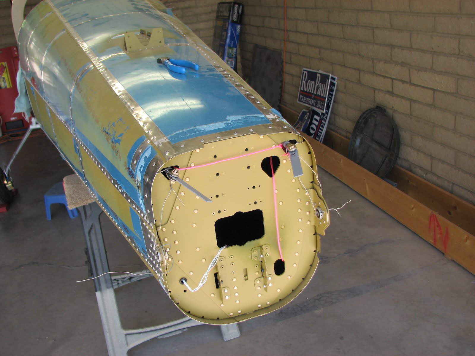
I've also decided to leave the strings in the tailcone until right before certification. It's easy enough to cut them and pull the string loops out, but it would be a major PITA to get these routed again after taking them out too soon.

Next I covered up the instrument panel so I could put the canopy on for fitting the skirt.


This was the first time since the installation of the avionics that all the screws were in and I thought I'd take a closer look.


I think the silver screws look good on the flat black. However, the upper curved row of screws won't be visible because of the forward tube of the canopy sitting right in front of them.

The first fit showed that I needed to trim quite a bit more in the front to even be able to start tipping the canopy. So back off, more cutting and back on. This is the second trial.


The solid silver area was about to get removed.


At this point I stopped the session as it was getting to a 100F with high humidity as the monsoons have arrived in Tucson. I now have to slow down on the trimming to not remove too much at once. I hope I can do some more trimming during the week.

The tailcone stub needs to get done and the electrical wing connectors have to get installed. Both jobs I can do on my own if there's no help available for working on the canopy.
Also, the money for the engine is on the way to the checking account and I hope to be able to send Van's the order along with the check some time this week.

Friday, June 8, 2012

Stabilator Installed

In the morning I passed my ground part of the BFR, the flying part had already happened and so I'm current again.
Back home I got to work on the stabilator. With the sawhorses and some additional stuff to prop it up enough and a bit of patience the stabilator came on pretty easy.


Some noise next to the driveway caught my attention.


A baby quail following the rest of the crowd and Mommy- I must have disturbed them. The eggs it passed were quail eggs that didn't hatch.
Back to work. Connecting the cables to the horns was actually easy despite the washers that had to get squeezed next to the horn and in between the forks.


Then I took somewhat more than half an hour to put the large cover in place that holds the bulkhead in place when the cables get tensioned. There are really a lot of screws going into this thing!


Now the second turnbuckle went on both sides of the cable ends easily. I tightened them by feel and checked both cables with the tensiometer. It's the blue scale that applies here and the reading is at the 6 o'clock position. Right on 40 lbs. I should mentions here that Van's got back to me about the groove problem. Reality is right and the plans are wrong. They said "they had not gotten around to correct the plans yet" and provided me with a link to VAF where the grooves were discussed before. So is VAF now the official Van's Tech Support forum?


However, taking a close look at the cables and their routes through the belly, I was not happy. Not happy at all! It seems that the further to the front the more the cables want to chafe, at the edges of the holes they are supposed to pass. The upper one is particularly bad and is indeed touch with quite some force and the very front hole. There's no way of adjust anything in that respect so I am a bit at a loss here.


Also, all the cable ends are outside of the turnbuckles more than the three threads Van's was asking for. If I would screw them in deeper, the tension could easily be double the requested amount.


The elevator feel on the stick is nice though. No feeling of sawing the bulkheads in half, no chafing noise or anything. I will ask Van's what they think about this but I sure won't get an answer before Monday. Also if someone here has a comment, please leave a message with your thoughts!
I will have to take the stabilator off again anyway as it is way too big to work around in the carport. The same is probably true for the rudder but only because the entrance is to low to allow the fuselage to get pushed back far enough to have enough room for the engine installation. And I do want to have the firewall inside the carport and not halfway outside in the sun.

A bit frustrated about the results, I resorted to stuff I can control. I riveted some nutplates on the tunnel cover that will hold the flap handle arrestor.


That at least turned out very nice.

Tomorrow I will take the stabilator off again and store it until it gets hauled to the hangar that I will rent starting next month. I believe I might build one of those temporary garages/sun-covers so I can get my truck out of the sun. If there's still time I will start the trim work on the canopy.

Thursday, June 7, 2012

Prepped for Stabilator Installation

In the morning - pretty late as I worked until midnight - I crawled back into the tailcone to measure the OAT resistance from the Molex connector end. Same result The OAT probe and the wires are fine. Here's a picture of the PFD with the problem showing itself ("OAT ---" in the lower right hand corner above "(HDG)").


After another trip into the tailcone with the same results, I tried to wiggle the plug a bit while it was plugged in and watch the PFD. Sure enough, when I was pushing down the plug, canting the pins a bit the OAT immediately got a reading of 34C which is close to the 94F I was measuring with conventional thermometer.
I contacted Dynon Tech Support and they are shipping me a new assembled connector with wire ends ready to crimp to the installed cable. I hope this resolves the issue. They say they never had to replace the male plug installed in the ADAHRS - yet.
So then I pulled the aft parts of the elevator cables ithrough the tailcone. Everything went well on that part,


I marked the threaded ends so I wouldn't confuse them while routing them through the fuselage part.


Connecting those dreaded turnbuckles turned out to be a major part though. Whatever I tried I could not connect the cables as the plans stated. They explicitly asked for the grooved side of the turnbuckle to point to the friont of the aircraft. The text is clear and so are the figures depicting the groove on the short side of the cable. The page 32-14 is revisioned and so I believe it to be true. However, the turnbuckle only goes in with the groove on the aft side. That's true for both cables and so I don't believe this is a coincidence. I searched VAF after this episode and it is confirmed that everyone had the same issue. I emailed Van's pretending I didn't check the forum and will see what they say.


Here you see one cable connected with the grooved side pointing aft.


The other cable is not long enough to connect it yet, so I tried the turnbuckle on each side separately. In the picutre you see it connected to the short F-1247A cable and the groove is pointing away from it.


In order to finish the rigging, I need to connect the stabilator and connect the cables to it. So I prepared the installation by setting up a rest for stabilator to sit on while will be fiddling the bolts and the WASHERS in.


As you can see the bolts are pretty well aligned with the bearings they are supposed to go through. This should be helping a bit and might even be able to connect it myself this way.


Tomorrow morning (after another work shift till midnight) I'll go to ground school and see if I can pass my BFR. I might try to connect the stabilator then as I don't know what else to do at this point. I need the rigging done in order to continue, so I better get this out of the way.
I haven't yet decided what to do about the wing electrical connectors. The old system was and is a joke, but I don't know if the new one is really much better. It certainly is work and it doesn't improve my idea of putting in trailer connectors with some slack to connect and disconnect them when putting the wings on and off. I am pretty sure I don't want to run an extra wire for the nav lights alone. It's extra weight and I have never ever used the lights without the strobe on my other plane. I don't think it's worth the effort and if I change my mind I can always add it at the first annual.
Things beyond the rigging? Trimming the canopy!

Wednesday, June 6, 2012

Antennas Installed

In the morning I went flying with H.L. to find out if I still have it. I probably do as I am alive to talk about it. The plane is a Eurofox which is pretty close to an RV-12 flight characteristics. Very light stick forces, very response, Rotax engine and almost no drag to slow it down.
I still have to put some ground school in to get my BFR signed off but the flying went well.

When I came back I tried to analyze the OAT problem. I figured I might have messed something up during the installation yesterday with all the soldering. Turned out that's unlikely as I measure a 7120 Ohms @ 92F between the sole two wires that connect it to the ADAHRS. No short, no broken wires. I have to admit that I am getting a bit uncomfortable about this whole glass cockpit stuff. And annoyed too, that I have so many issues with.
I am talking to Dynon Tech Support and they confirm that the resistance I am measuring is about right for the temperature. I measured at the splice connectors, so theres still the chance that one side of the splice crimp is bad. I'll crawl back in there tomorrow morning and measure at the Molex.


This was my setup for the tail cone access. A plywood board and a rag as cushioning. It worked ok and nothing got bent.

After the OAT check I retrieved the rudder attach plates from priming and installed them on the rudder pedal horns.


The VHF antenna was next on the installation list. I had some trouble attaching the coax cable as it wanted to bend in a way that would have chaffed on the elevator cable. I ended up zip-tying it to the main wire bundle to hold it down. The actual antenna installation was easy as I had installed the optional nutplates and didn't have to mess with the nuts in hard to reach places.


The transponder antenna installation concluded Section 42C and the avionics installation as a whole. However, I still have the task open which requires me to register the ELT. As I don't have a tail number, I assume this will get done after certification


I'll be running the Stabilator cables to the aft end tomorrow morning. I want to hold off on the installation of the elevator until I have Elizabeth to help me with it though. Not sure what else to do until then. The canopy needs trimming work done but that also requires two people...

Tuesday, June 5, 2012

OAT Installed

I drilled the rudder attach plates when I came home. The distance of the hole positions is 1" and this is fine according to the plans.


They looked a little banged up after drilling and trimming so I primed them again. The primer was still drying when I wrote this so tomorrow I'll add a photo of the finished parts.
I moved on to the OAT installation. This turred out to be a bit more time consuming than I had hoped for because I chose to not install when routing the wires as I wanted to keep the plane on the left side. The left side is also where the OAT would have pocked out so I decided to determine later how to install it.
Drilling the hole was the easy part.


The electrical diagram showed a simple two wire connection so I hoped for an easy installation in form of cutting two wires, install the probe and then solder the wires back together. It turned out that the cable was composed of 3 conductors and one shield.


I cut those wires, installed the probe and soldered the wires back together, reinstalled the shield with aluminum foil and isolated everything.


Everything looked good but when I powered up the SkyView I did not see any temperature readings. As a matter of fact I couldn't remember if I've ever seen any readings. I wanted to check on some older pictures I had taken during the Avionics problems but it turned out that I never took a picture of the primary flight display. So I cannot say if the probe had worked before my installation or not. It was getting late so I deferred further investigations to another day.
I will have to unplug the OAT from the ADAHRS and see if there's either a short or an infinite resistance. Anything else should provide some form of temperature reading. I saw that only the blue and yellow wires are used, so I should be able to trace the problem down if it's in the wiring.

UPDATE: I crawled in the back and measured the resistance between the blue and yellow wires. It looked good, the meter showed 7.12 kOhms and I believe that is a reasonable value. Anything between infinite and close to zero should be fine. Why the ADAHRS is not reporting temperatures, I will have to find out. Maybe reading the manual could help, maybe the Dynon forum has something about it.

Sunday, June 3, 2012

Rudder Installed

In the morning I had the joy to remove the left and right torque arms. I put them on the work bench and prepared them for match drilling the belly side holes.

That was easy. Opening them up and drilling them through with a #12 bit needed a bit of thought. I chose the drill press for a straight path for the bolt that will later get installed.

With some Boelube the drill bit went right through without a hitch. After the deburring the pieces looked like this.

Installing them back in the belly, along with the torque tubes, was harder than taking them out. I hate those washers on the inside of a bracket. I glued them successfully in place with Superglue. That made it a bit easier.

After lunch I pulled the ridder cables through the aft bulkhead using the rope I had routed and affixed to the tail cone almost 2 years ago.

I temporarily attached those steel plates to the cable forks.

Then I attached the vertical stab to the tail cone. It is not an illusion that it looks like it's taller than the entrance of the carport. It definitely is too tall. I also had to move the fuselage way forward to clear the stab and the rudder, so I might have to take the assembly off again until I get to the hangar. I wouldn't be able to install the engine otherwise.

Here's a better shot:


Installing the rudder was a nightmare. The glued on washers wouldn't stay on because of too much lateral force on insertion and I couldn't get a finger and a bolt in on the top hinge. Fiddling with pliers didn't give enough grip to force the bolt in. After half an hour I finally succeeded by accident. This is probably the worst part of the assembly so far.

I centered the rudder with a string once it was installed. The strings follows a rivet line on the rudder and ends on each trailing edge of the stab. Measuring the distance between those two points divided by two gives you the center mark on the string. You also mark the ends of course. Then hold the end marks on the trailing edge and adjust the rudder with the tip of your nose until the edge of the rudder is on the marked center spot on the string. I verified by eyeballing that I wasn't all off and clamped the plates to the rudder horn.

In the cabin I had the pleasure to install Denny Myrick's gift he gave me at our last meet at the airport - his rudder jig! He saved me a lot of time building this piece. Thanks again for this, Denny!!!

I pulled pretty hard when tightening the ridder cables but it didn't feel like the left one was giving much. The right one came out significantly farther than the left one. So I checked on the inside if there was slack on the left cable. Nope, not as far as I can see.

However, when I unclamped them after marking, they looked like this.

I will have to check with other builders if this deviation is common or if I made a mistake here. So until then I will hold off on drilling them.
Update: Bill and Dave confirmed this is a reasonable difference that reflects the difference in the rudder horns on the pedals.

Not sure what next to do. Tomorrow I have to go back to the paying job and I believe rigging the stabilator is next. More fun with washers I believe.