On Thursday, I manufactured the clips that will hold the fuel return line to the top skin of the tank. It would have been an easy job had Van's provided the material. I thought I had seen a strip of aluminum for this purpose but as much as I was browsing and searching the list of contents for the bags, I could not find it. A part that small must be either in the bags or was a leftover from a larger part where most of it was used elsewhere, alas I could not remember where I would have put such a left over. Either way, I had no material and studying the drawing I thought I scrounge up some skin pieces from the scrap bin. I did so and cut and bent the piece to shape and created some beautiful clamps - only to find that I had overlooked the material thickness laid out in the drawing. It said .032 and I had used ordinary .025 from a skin. So back to the scrap bin and retrieving some .032 parts this time. This is a rare good but after a while I found a suitable piece and went through the manufacturing process once again.

Then I manufactured the return line inside the tank. I cut the tube to length, allowing for a lot of excess material (final cut can happen once installed). Flaring one end was simple and I installed it on the fitting. Making those bends inside the tank was not really hard to do and it helped determining the correct position for the bend by eye-balling the height from the side of the tank.
After the first bend I put on the top skin with a few clecos to determine where I had to make the upward bend to guide the line into the filler tube.

I marked the position this time (pretty close to the cutout as the bend takes a half the diameter of the opening), removed the skin and bent the tube. Then I put the skin back on and also put the flange in position to determine how much of the tube I had to cut off.

I cut off the tube and deburred the end, then removed the top skin.

That was the result of Thursday. I had also tried to rivet in the ring for the Moeller gauge but this attempt failed miserably. It turned out that I had no good flat surface that was also strong enough to not dent when hammered and allow the skin to rest evenly at the same time. I ordered a steel plate at Amazon to try again.
The steel plate arrived on Saturday and that's when I went back at it. With a little effort I was able to get those countersunk rivets set without pushing them out in the process. I held the nutplates in place with their respective screw after alliging the rivet holes with clecos.

As the final installation will be done with Pro-Seal it doesn't matter if the rivets are really completely flat with the surface.
This is how the inside of the tank will look like.

On Sunday, today, I finished the tank work by pre-installing the fuel sender and scuffing up the flanges that will get prosealed and riveted next. Bending the steel wire to plans was easy with a vice and a hammer - but, hey, I have a lot of experience since the flaperons when it comes to banging the cr*p out metal!


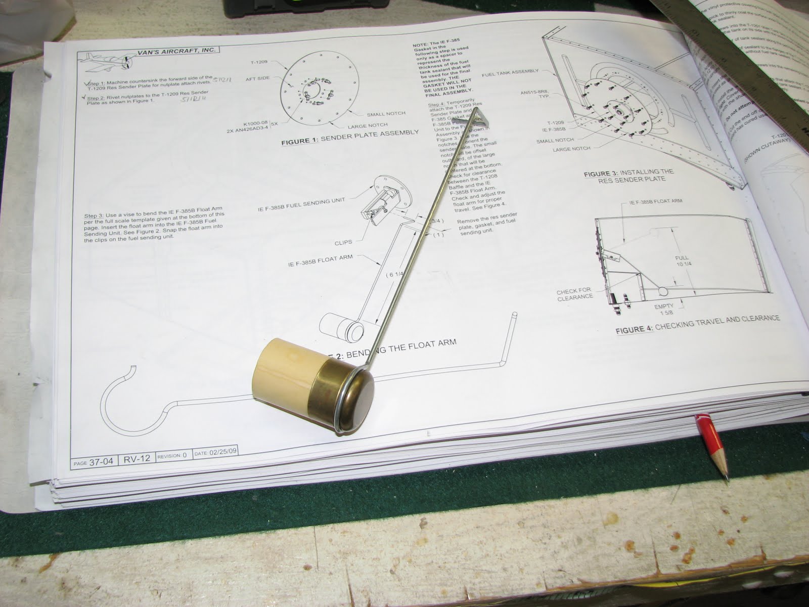
That done, I had to verify that the sender arm wouldn't contact the cross baffle, so I installed the sender for a trial fit.


As you can see the baffle was not an issue. I could easily put my finger in between the baffle and the wire without lifting the floater. I also measured the arm movement and I came quite close to the values listed in the instructions. In lowest positions the top of the floater is 1 5/8" above the tank bottom. At the highest position this measures 10 3/4", 1/2" more than in the instructions.
Then I went on and made two candles as Dave called them. If you're unfamiliar with Dave's recent blog entry, he was talking about the flaperon push tubes.
After cutting, deburring and truing the cut of the tubes, I marked the center of the holes to drill with blue tape. I have some aluminum brackets to hold pipes in a vise which came in very handy now.

I drilled the hole through the tube so it exited in the other side to reduce the number of alignments (and curses) I had to do. To make sure that the second set of holes would be close to be "evenly spaced" with the first set, I used this little trick (look at the head of the bolt):

The result looked like this.

I prepped and primed the parts and riveted them together (make sure mark them before taking them apart so you know which stub goes into which end of which tube!) and adjusted them for correct length.

The tank is now ready to get its finally internal cleaning and then I can goop the parts together and pray that the pressure test after it fully cured will show that it is indeed not leaking. I might be doing this tomorrow morning ...


No comments:
Post a Comment