Monday, January 11, 2016

Yet Another Annual

The plane is down for inspection since December. I am by no means ready to formally document everything yet but there was one issue I should inform readers about before they run into the same problem.
The nice blue air filters I had installed during the last annual (and which appeared just fine in March when I installed the Ducati regulator) both showed cracked bodies just behind the attachment flange. They were both cracked almost to 50% of the circumference and clearly did not provide much filtration at that point. When I removed them, I found that the rubber appeared to have worked its way into the serrations of the hose clamp that was holding it on, on both. One was so deeply connected that it ripped the rubber of when I removed the hose clamp. It almost looked like the rubber or plastic was not able to take the heat under the cowling as it looked partially melted into the hose clamp.
I was about to order replacement filters from the same place and am happy now that they ran out of stock. That gave me a moment to reconsider that they might just not be the best solution as an aftermarket product anyway.
I found a smaller sized K&N but decided to give Green Filter a chance. They have one model that just fits the Bing flange and I like that it is a fully paper/rubber model with no metal parts.


It has a pretty nice clearance and a very good fit to the rubber flange of the Bings. Actually, I had taper the inside of the filter flange a bit to be able to get them to slide on. The type number is 7069 and it appears to be only one that would fit the Bing inlet. Let's hope this one holds up to the vibrations better than the blue filters.

It was also time to replace the spark plugs. I did not do it at the 50 hour mark as they looked prestine. I just cleaned them and put them back in. They still did not look like they needed replacement but I did notice a deeper drop during the 4000 RPM ignition test in the last months, so I went ahead and threw them out.


Of course I had to try something new for the replacement, so I installed the Iridium version of the same DCPR8E plugs which have an EIX suffix. They are a bit pricey but then again they go into an airplane so we are used to overpaying, right?
The result by the way was amazing. The ignition test dropped the RPM only by 50 instead of 70-90 with the 8E plugs. We will see how they hold up and if this deteriorates over time but for now I think they might be worth it.

I might have to improve the air scoop for the voltage regulator as the temp indicator hit the lower mark so far and I don't believe she flew a lot during Arizona's hot summers....


One of my concerns last year was the plastic buffer in the tail cone that should keep the lower cable for the elevator from sawing through a bulk head. It was worn down very close to the metal and I had greased it with silicone grease to reduce friction.


I pushed the cable out of the way to get a better shot of the actual friction area and it looks like it did not deepen any further since last year. If it was touching the metal the primer would have rubbed off and there is no evidence that this is happening yet. I just re-greased it and will check again next year. The tension of the cables held up pretty well too and I did not tighten them.

One of the improvements this year was to finally add the APRS radio beacon. I am a licensed Amateur Radio operator, so it was just natural to put that license to additional use with the RV-12. I took quite some time to choose the right antenna for this project. I had an antenna from DeltaPop Aviation but was afraid that it was too heavy and catching too much wind load for the super thin skin on the bottom of the tail cone. I looked into mobile Amateur Radio antennas and considered different antenna bases and so on. After long deliberation with myself I decided to go back to the initial thought of using the whip antenna from DeltaPop Aviation. It is exactly tuned to the APRS frequency, has a matching network that eliminates static build-up and it is proven to survive the 120 knots TAS of an RV-12. The mobile antennas won't get used much above 80 mph and their radiator could separate from the base and fall off the plane if the set screw ever gets loose. All I needed to do was to properly reinforce the skin on the bottom of the tail cone to avoid vibration cracks over time.


The little fin is the PCAS antenna that I had installed last year. I finally hooked this one up to the Zaon MRX unit this year too. The base of the APRS antenna is 4 feet away from the base of the VHF Com antenna and I only had to slightly increase the automatic squelch of the SL-40 to not open up when the beacon sends a position (from 56 to 75).


So you can see that I took the reinforcement very serious. The large sheet is 40/1000" thick and a foot long, I put the transponder reinforcement plate on top that came with the RV-12 antenna and which we never used and I also installed some left over angle on the perimeter of the base sheet to stiffen it up while keeping it very light weight.


On the interior I did not get very fancy for now but it might turn out to be a good spot anyway. The Byonics radio was attached with cable ties to the tank fill spout (some foam in between to dampen vibrations). And the GPS antenna for the radio was riveted to the center bracket of the rear window to give it a good view of the satellites.


The only required switch on the dashboard is a breaker of 3 Amps that is labelled "Beacon" which I felt was quite accurate.


It worked right away when I switched Main and Avionics on. If you would like some advice on where to wire this into the existing 12V bus without causing a fire, just email me.
As you can see the Zaon MRX was finally installed too and it is connected through the 1 Amp breaker to the Avionics bus. So far I have not seen a case where it would have detected traffic when ADS-B did not see it but I haven't been flying in rough mountainous terrain yet, so the jury is out if this PCAS install was a waste of time.
The APRS beacon works great and you can now follow the travels of N128TL by following this link.

Besides adding stuff I was also able to determine the cause of my problems with the EGT sensors. The sensors work just fine but the wire of the right sensor (on the sensor side) had vibrated off. The stiff wire of the sensor harness is not just hard to reliably crimp a connector too but is not itself not very happy about vibrations. I did a brute force approach with a tube of red solicone to address that after soldering (yes, yes, I know, we will see if it breaks again) an extension to the broken harness wire.


I just smothered the EGT temp wires in a layer of red silicone in the hopes of softly reducing the vibrations enough to avoid future breaks.

This should have been the last item on my list but then Dynon announced the release of the GPS-2020 that would be the last piece in my Avionics system to be fully 2020 compliant. I couldn't pass that chance up to replace my current GPS while the plane was all opened up now, could I?
Dynon was very quick in delivering the GPS and I figured from the RV electrical schematics that this was a drop-in replacement. As I did want to reroute the 4 wires through the firewall, I just cut off the wires of the old GPS and soldered the new wire harness to the existing wires.


Getting the old GPS out was a hassle. The metal lock screws are almost impossible to hold well enough to turn the bolts. I ended up dremeling the case of the GPS back to I could get a wrench on them. The GPS still works but sure doesn't look so good now. Oh well.
Please note that you do need to upgrade your SkyView software to V14.0 or beyond to be able to use the GPS-2020. And you will have to go into the setup and manually make all the changes to make it understand that the previous GPS has been replaced.


I also checked that worrisome Service Bulletin item about the flaperon torque base in the tunnel. Sorry I can't remember the exact phrasing or the number right now. It's the one where an aluminum bracket starts developing a crack from a rivet hole after around 200 hours of operation. I took photos and they show no issues yet at 113 hours.


And the final installation was a piece of plastic that I designed and printed out on a side project I completed in December last year. It's a Kossel 3D printer and it allows me create neat stuff that would be hard to find otherwise. In this case it is a headset hook that allows me to finally have a good place for my Bose headset while I am away from the RV.


This is a prototype and I am trying 3M double sided tape on the back (the red type) but I a mnot sure if it will stay there when the plane heats up in the summer on the tarmac. So I will design another one that takes rivets for installation - just in case. Anyway, for now I am very happy that the headset is nicely stored under the avionics bay and out of the sun.

Monday, March 23, 2015

Replaced the Ducati Regulator

My Ducati Regulator/Rectifier had started to show signs of upcoming failure. It had not reliably charged the battery on the ground while running at low RPMs after initial engine start. It seemed to have worked ok once in the air and for subsequent engine starts during a longer flying day but other have reported this behavior before the regulator eventually failed.
So I decided to not wait for that failure and to replace it. I also wanted to address the obvious reliability issue with this regulator as well as improve the cooling issue with the air pick-up from the cylinder head plenum which does apparently not provide enough air at low RPMs on the ground.

After a lot of research and consideration I decided to go the most expensive route. I had initially settled on an aftermarket Harley regulator from Compu-Fire (55120) which I still believe to be a very good solution. However, the installation of said regulator would have required wiring work (to adapt to the existing Rotax plug) as well as mechanical work to provide an adapter plate for mounting and to rebuild the metal cap to control the cooling air flow.
I eventually found a better solution that would not require such work, or so I thought. The regulator is from a company in Germany (and before you ask, at this time they do not ship outside of the European Union, but I will be talking with them to solve this issue) called Silent-Hektik. They provide a wide variety of regulator/rectifiers for different application and also one for the Rotax 912/914 series (English translation) of engines. They also supply regulators for Jabiru 2200/3300 engines and even for common auto/motorbike conversions (at least common in Europe).
(Edit: Back when, I ordered the F4112 which seems to be replaced by the F4118 now)

This past weekend, I decided to put it in. Unfortunately, I forgot to bring my cell phone on the first day, so I could only take photos on the second day when everything had already been installed, trying to catch as much of the installation as possible.
Removing the Ducati regulator was fairly simple. I had just removed the upper cowling and that was sufficient, albeit without the lower it might have been somewhat easier.
Getting the Silent-Hektik regulator in revealed two stumble blocks. While the case has the same outer dimensions as advertised, the top has one cooling fin more than the Ducati. This required either to rebuild the top cap or to bend it open and wing it. I opted for the latter. I also installed a flange on the cap, moving the hole over to the center. The flange allows for a 1" SCEET hose to attach with a worm clamp. The flange can be found here.

Take a close look at the corners of the cap in the following picture. I resealed the holes in the corners with silicone.


The other "issue" is that while the mounting holes on the Ducati are a lot bigger than you could ever need them to be, the Silent-Hektik has holes that are probably meant to be used with metric M5 or M6 bolts and an AN4 bolt will not fit. Of course, this is what Van's chose to mount the regulator to the firewall shelf. I drilled the holes open with a drill bit size that allowed for some slack of the bolt and it lines up perfectly with the existing nutplates on the shelf.

I wonder why Van's chose AN4 bolts as holding the regulator to the shelf is clearly not requiring a lot of force, but it already presented a problem with the Ducati as there was hardly any clearance to get a socket over the head of the bolt. It is even worse with the Silent-Hektik regulator as they really used every possible area to contribute to cooling the regulator and that means you will need a 7/16" crow foot to get this baby torqued down. With AN3 bolts the socket would have likely cleared just fine.


These were the only issues that I ran into that would make this installation not quite a perfect drop-in replacement. The plug fit like a glove though and snug right in and that is what I most cared about.

By the way, when I removed the Ducati regulator I could not see why it is frequently failing in this application. I had recently attached a temperature sticker on the side of it (around 50 hours) and it did not show a significantly high peak temperature.


It showed that it had reached 160F definitely and did not exceed 170F. Now, this is not a temperature you want silicon to operate at for a continuous time AND Ithe sticker was only on it during the cooler months in Arizona. So, yes, I can see that running it at 30-40F higher ambient temperatures could push it into the death zone.

The plug and the connector looked good though, no heat damage from high currents through bad connections or anything.


To avoid this overheating from happening again, I removed the existing plastic hose and plugged up the plenum pickup with a piece of scrap fiberglass glued on with silicone.


Not pretty but will definitely do its job. I also installed another temperature sticker on the Silent-Hektik.


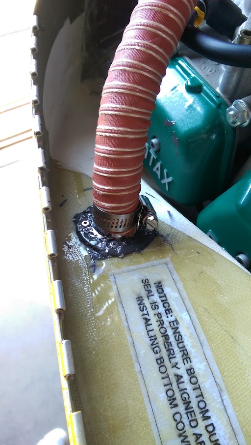
For the new air pickup I drilled a hole in the top of the radiator tunnel and glued on another 1" flange using Pro-Seal.


The white insert in the flange is a piece of PVC tube that I glued in with silicone (so I could remove it later if I decide to install a scoop to increase pressure on the cooling pickup). From the tunnel it looks like this:


I hope this will help to divert air to the pickup line and increase flow during low RPM on the ground. I am currently at 87 hours and my next oil change is coming up. At that time I will check the temperature sticker and decide if need to install a scoop. If so, it will help to have the lower cowl removed and work on it from the radiator side.

As the Pro-Seal needed a day of curing before putting any stress on it, I had to return home at that point and let it sit.

The next morning I came back to the hangar only to find that the story about keeping Pro-Seal in the fridge to keep it from expiring are not true. My can had an expiration date of late 2013 on it and I kept it to do simple sealing jobs that would not require fuel resistance but where you wanted the paint-ability of the Pro-Seal. I kept it in the fridge ever since I used it for sealing the tank and the firewall in 2013.
Well, it does not cure anymore, at least not within 18 hours as the it used to. I know that it needs longer to fully cure but I would have expected it to be at least strong enough to hold the force of a bent SCEET tube. It did not and the flange was pulled off and tipped forward almost immediately after putting it on.
I had 3 options at that point. Remove the gunk and glue it on with 5-minute epoxy. I did not want to do that as the 5-minute epoxy gets brittle and could crack and break under vibration. I could wait and see if the pro-Seal eventually cures after a week. Not too excited about that idea either.
I could riveted the flange on and care about the Pro-Seal. That needed two people though as one would pull the riveter from the top of the tunnel while a helping hand would hold the washer on the shop end of the rivet that would relieve the stress on the thin fiberglass of the tunnel over a larger area and avoid cracking under vibration.

That very moment my friend and hangar neighbor Tim landed his Drifter and got ready to push her back. 5 minutes later the flange looked just fine with 4 rivets holding it down.


The last steps were to find a good path for routing the hose and to put the tie wraps back in place keeping everything tight together. The SCEET hose is 3' long and fit perfectly without any trimming.


It was still early enough to take her for a spin and I wanted to see if the regulator was doing its job. I pulled her out, jumped in and started the engine. While the Ducati needed at least 2500RPM at this point to drain the battery at only -1 Amps or just be at +/- 0, the Silent-Hektik presented me with a much better picture:


It charged with even more than 2 Amps before I could my phone out to take this picture. And all that at the lower range of the green arc. Perfect!

In flight I saw the voltage rising higher than with the Ducati. The Silent-Hektik charged the battery to 14.3V max. and kept it at 14.1V most of the time where the Ducati would be showing 13.7-13.8V. I heard that going for the higher voltage should enhance the battery life and maintain its performance by keeping the plates clean.
We shall see...

After my next oil change I will follow up and let you know how that air pickup is doing.

Tuesday, December 23, 2014

So I did not post trip reports

I really had the best of intentions when I last posted in May this year, to keep you folks updated on how nice it is to have a flying plane and why one would want to get one started (so they could eventually go to all these cool places we went to). But then I figured that I just did not have the time anymore to sort through all the photos taken and come up with a nice catchy story to bind it all together into a nice blog entry.
I just don't have Dave's inspiration (Schmetterling's Dave) and energy to keep this going on a detailed level... but, hey, this was meant to be a builder's blog anyway, right?

Well, then why am I posting now?

Hm, you might have guessed it if you followed me for a while. A bit more than a year ago I got my "pink slip" and that means that I needed to do an annual inspection of my RV in order to honor my operating limitations.

And so I started over Thanksgiving on this task to disassemble and inspect and to catch up with some SBs and stuff I wanted to change myself.

Taking the cowls off to perform the mandatory oil change (after just 50 hours since the last one at 25 hours) was somewhat revealing. I found that I had no problem with chafing wires but the modification for clearing the left forward exhaust spring was not deep enough. It still has a very slight contact it seems.


Not enough for me to consider another lay-up but I might ever so slightly Dremel it down if it persists.

Then there was a slight oil leak at the oil drain plug. Obviously the crush washer is very delicate in regards to its placement when tightening. It was just a few drops over the 50 hours but due to the vibration got tossed around quite a bit.


All the temp indicators showed that the ignition modules did not get too hot. I also added another indicator on the side of the rectifier/regulator to see if it runs too hot as others have reported quite some problems with the Ducati unit.


After the oil change it was time to put the plane on saw horses. Before that I had removed the wings and put them back in the cradle.


The wheels and brake assemblies came off and I found a slight mark that shoeed some contact between the brake disc and the spacer for the inner pad on the right brake.


I contacted Matco about it and they said not to worry about it if I can clearly determine that it does not make contact with the disc now - which it doesn't. I will keep an eye on this. The linings where pretty worn by-the-way and would not have lasted another 70 hours, so I replaced them.

I cleaned the bearings and repacked them and everything went back together and off the sawhorses. Before that I also retorqued the landing gears bolts which needed absolutely no attention whatsoever. They were in perfect shape.


On to the interior. I took off the floor covers and found absolutely nothing to worry about.


Besides some dust, the tail cone did reveal something though:


It looks like the plastic spacer that is supposed to keep the lower elevator cable from sawing through the bulkhead is worn down quite a bit. I measured about 3mm left and the cable makes no contact with the bulkhead yet. This is something I will keep a close eye on and I might have to replace that spacer some time soon.
The tension of the elevator cable was below spec at 20lbs and so I put that on the list to tighten when the seat pan was closed up.

Back to the engine. I replaced the K&N air filters which started to discolor already with a pair of blue ones from Simota USA. They cannot be worse than the K&Ns and they are a bit shorter too, which gives a tad more room to work with under the hood.


I also had to replace my extra RPM resistor as it had started to show erratic readings again. Its behavior indicated that the crimp was probably loosening and removing it confirmed that suspicion. I replaced it with another crimped installation but I might have to additionally solder the connection or install a wired version to overcome these issues.


Next was some electrical work on the left side, enhancing the headset wiring with a LEMO connector for my Bose headset to get the power from the onboard electrical system.
The cutout for the plug reminded me of a delicate surgery performed with a Dremel tool.


Thanks to Van's we have a power wire in the correct location that just ends dead as the standard plugs do not provide power to a headset. But Van's knew what builders would eventually like to add down the road.


It took a while to get it all separated and then soldered back together without messing anything up. Here you see the wired in LEMO harness all hooked up except for the red power wire.


And then all installed in the fuselage.


It all worked like a charm, with a regular headset or a LEMO plugged in. Noticeable is that the headset power comes on with the Main switch, so the LEMO is powered as soon as you power up the system without needing another switch like the Avionics system or anything.

It was a full weekend worth of work but definitely worth the extra effort.


Then I repaired some things with my backup avionics. The Chinese altimeter had given up about 6 weeks after starting flying. Like so many others had reported before (I just couldn't believe it could be THAT bad) the thing never showed the right altitude after it went bad. The Kohlman dial did not seem to have much of an effect anymore and it was practically useless.
Also my German ASI had come back from repair (my fault when running the leak tests on static and Pitot systems) and I wanted to put it back in the panel again.

Opening the avionics bay revealed .... nothing. Everything looked just like I had left it there.


Out came the crappy altimeter and in the one built by United (yellow-tagged) and in with the ASI as well.


The German plugs are a bit too undersized to use 1/4" ID tube and get a good seal. I tried RTV before with success but this time I did not succeed with it. No big deal, I just used shrink tubing to make them a tad bigger.


Please note that the plumbing in the picture above is actually glued to the glove box using spots of RTV so it cannot move around or vibrate.
The disconnected breaker and the still covered slot above the ASI is for a PCAS unit which I chose not to install yet. I might do that the next time I have the bay open. 

Before closing the avionics bay again I complied with SB 13-12-12 and sealed the avionics bay. Instead of using the awkward suggested method described in the bulletin and smear RTV on the inside of the joint after removing the Dynon from the panel, I used a thin compressible sealant strip behind the row of nutplates to accomplish the same goal which is to keep water from entering the avionics bay.


You can get this wonderful sealing strip in 3/16" width from Aircraft Door Seals in Texas. The product is called VWS 100. I also had a VWS 150 which is 1/4" wide as I did not know back then which size would work best. I used the VWS 150 under the canopy skirt to seal off the minor gap between the skirt and the avionics bay cover to keep water and air out. Sorry no picture from that installation yet.

Next, I closed up the seat pan and went on to tighten the elevator cables. Make sure you have the safety clips for the turnbuckles handy when you cut them open.


I tightened the upper cable as this was the one most loose and it also had the most threads showing out of the turnbuckle.

On to the last two items on my list. I wanted to inspect the gascolator screen and thought it to be  a good occasion to drain the rest of the gas out of the tank to allow for the Dynon tank calibration that I had never done. The Moeller gauge is so easy and reliable that I never felt I needed the Dynon gas level information anyway.

It was also a good catch-up on my still existing gas pressure drop issue when cruising with less than 8 gallons of gas.

With the gascolator bowl removed draining the tank through the gascolator is easy. The pump makes it super fast, so watch the level in the canister!


As you can see above, the pressure drop is a clear mystery to me. This flow is taken at around 2-3 gallons left and the pump on.


There was a bit of debris caught in the screen, a bit of fluff that looked like Scotchbrite fibers but the rest was mainly excess lubricant from the O-ring. As the stuff is fuel resistant, it doesn't wash through the screen. I thought about cleaning the screen but they cost $2.50 at Van's and so I just replaced it.
I also had to replace the O-ring as its inner diameter had extended to match the outer diameter of a new one and would have hardly fit back in. This is the result of ethanol in the gas I am using for the Rotax.


And then on to the final task - installing the turtledeck brace that was added to Section 42C. By itself a very simple task but pushed at the edge of being impossible by the inaccessibility of the tailcone without removing the tank. My aft bulkhead modification allows for easy access only to check the cable tension or maintenance on the ADAHRS and its connections but not really for crawling into the cone while on your back.
Of course, that was exactly what I had to do - and then some.

It was insanely difficult to balance on your side while having only one hand to work on a part that needs to be affixed for match drilling as it only has one cleco point in the beginning.

I eventually succeeded but not without major bodily pains that lasted for two days to remind me to never do that again.


And after an hour of sloshing fuel around (I did mention before how much I enjoy that, right?) I also completed the gas tank calibration task that was part of the PAP.


One thing I found that is not yet resolved. Just when I was closing up the aft bulkhead to go for the maintenance flight I found a hole that looked like a #30 size (years of riveting engrained this particular hole size in my cognitive/perceptive cortex).
A hole that might need a rivet but there was clearly no rivet in place - whence the hole.


You found it? It's on the right side of the angle the tank attaches to. Now clearly this would have to get riveted in from the aft of the bulkhead and I had already put most of the screws in. Knowing that one missing rivet would not cause me to crash and burn I decided to look this up the plans and put it on the list for the next annual inspection.

And here she was after the successful maintenance flight. The RPM was again rock solid after replacing the previous resistor with a freshly crimped one. This time around I only had a 41k Ohms available instead of the 47k I had used before, and it did not seem to matter.


This work was done over more than 3 weeks, with all weekends spent at the hangar and some late afternoons and holidays as well.