Tuesday, April 30, 2013

Stiffener Spacer Riveted

I did not have much time to night but I was able to rivet the spacer parts onto the stiffener angle.


Clecoed and done.


I realized a bit later that I had used ordinary NAPA primer and not the stuff for engine enamel. I guess that in between two good heat conductors this should stay cool enough to cause an issue.
A closer inspection of the following steps and the access for removal of the one rivet below the gascolator revealed that there will be no short-cut. I will have to remove the bolt that holds the clamp for the cooler hose and also the gascolator bowl to get to all the holes and to remove that one rivet.

Monday, April 29, 2013

Stiffener Retrofit Started

You might think that in lieu of official Van's Service Bulletins I am now picking my own side projects just to have an excuse not to finish the project. Well, you might be right but then, this Stiffener Retrofit Kit appears to be a good idea to avoid official Service Bulletin work later down the road. And nothing that is related to the firewall would ever be easy to fix. Not as easy as now, at least.

So, I ordered the Stiffener Kit a few days ago and Van's immediately responded by mailing it. Tonight I took a closer look at it and started.


This should give you an overview of the parts included and the work involved. To inspect the side reinforcements, I removed the tarp on the fuselage and inspected the cockpit area. Not with an easy feeling I may add. I had not looked at the inside since I had reinstalled the rudder pedals after retrofitting their fittings with the appropriate thread sealant. So I was indeed a bit anxious about finding drops of brake fluid on the paper I had put under the pedals back then ....


Without any reason, as it turned out - to my great relief! Everything is at least tight enough to not drop fluid all over the floors. I did not yet do the wipe test with a fresh paper towel but I am a bit more confident to that these days now.
The real reason for this inspection was to take a look at the side reinforcements which will have to get tweaked a bit.

Access does not look tricky (nothing is tricky in there after removing and reinstalling the rudder pedals!). The firewall seal might get damaged a bit, but maybe it will work out ok.

The front of the firewall is a bit more delicate though. The center pop rivet in the following picture, which is partially blocked by the AN3 bolt protruding from below, has to be removed as it will form the end point of the stiffener angle that will get installed there.


The plans also call for the removal of the clamp that guides the cooling hose you see in that picture as well as the removal of the gascolater bowl. I will try to work my way around this as I believe it is possible to pass these obstacles with a longer drill bit and some care.
But first one has to prepare the stiffener angle. As this is a retrofit, we have to attach a spacer on the back of the angle to clear the dimples in the firewall which the newer kits obviously don't have anymore in this area.


The spacer is the part that has the vinyl removed and also shows the cut marks for separation of the part into 4 smaller pieces - after match drilling the #40 holes into the angle. So I clecoed the parts together.


While I was drilling away (clecoing with #40 clecos was not necessary as the #30s held the parts in place), a quail got really annoyingly friendly in the workshop area. So I took a break and inspected what the reason might be for that. I had a hunch and a quick step on the ladder confirmed my suspicion!


Just enough for a quail omelette! If you do not recognize what structure the bird chose for its nest, it is because I am too close. Let me step back a bit and you will see.


I am sure you recognized the stabilator now. The center wrapped up and all dusty hanging under the roof at the workshop. A great and secure place for building a nest if, IF, the bird would not mind my presence so much - which, of course, the bird should have realized before dropping 7 eggs right at the workshop entrance.
Oh well, snakes have to eat too, I guess. The bird would not settle down and accept me working alongside, so I cleared the nest and moved on to the stiffener.

Match-drilling completed, countersinking followed. From the firewall side, I want to add. The idea is to have the spacer riveted on the back so the back is a flat surface that will then sit flat on the firewall and get riveted to it through the #30 holes.


Before I could rivet the parts together, the spacer had to get separated, some material removed and everything had to get deburred.


Don't worry. The parts are unique after the match-drilling and the countersinking, so they will only fit on the angle in the correct way (Van's style, as usual). Before riveting, I decided to prime both sides of the spacer.


Now the parts are drying until tomorrow evening, when I will rivet them to the angle.

Sunday, April 28, 2013

Protractor Tool Built

To finish the propeller installation I need to make sure that the angle of attack of the blades are within a reasonable range of each other. Copying what Tony Tessitore had done before, I built a protractor reference tool like his.


As you can see, I used a scrap piece of aluminum angle that was left over from the longerons.It happened that one piece provided just enough length to built the whole tool. 


Cut the pieces and deburred them, trimmed to fit into each other and .... Voila:


If you have a very long protractor, you might want to countersink the central rivets that build the T. In my case that was not necessary.
A first test on the propeller back showed that it provides a very good base and easy repeatability. Now I have to mount the protractor and then finish up the propeller installation.

Monday, April 22, 2013

SB 13-04-05 Completed

That was a quick job tonight. I came home from the paying job and started immediately on the SB to reinforce the oil canister bracket.
Removing the can came first.


I did not remove the battery and it turned out not to be necessary - if you have an angle drill that does not need the room the battery is occupying.

Next step was to mark the outboard holes and drill them.


The rib was marked and inserted and drilled through the holes in the bracket. Outboard side done.


On to the inboard side which has to get drilled from the inside of the cube if you do not want to remove the engine. The angle drill with the longer bit is good on the straight side while the shorter bit that is also visible in the photo is needed for the angled side to clear the battery.


Straight side was drilled and clecoed.


And so was the angled side.


Then the rib came out again, chips were removed and the rib and the holes deburred. Everything went back in and clecoed on and ready for riveting.


Riveting was a blast. I just took care to still have access in case I would want to drill out the rivets. The outboard side was all riveted from the outside, the inboard straight side from the inside and the inboard angled side from the outside again.


Finally, the oil canister went back into the bracket and got tightened.


1 hour and 15 minutes after I had started the SB was completed. Not too bad but I still hope I do not get many more of these interruptions on my way to completion. No, I will not ask the question, if I will ever get done with this project. As I know the answer to this and I do not feel strong enough to face it today.

Sunday, April 21, 2013

Spinner Work Completed

Continuing the work on the spinner backplate, I countersunk the nutplate attach holes and deburred everything.


The same was done with the spinner front plate.


All the nutplates were riveted on and the outside flange deburred again to make sure that nothing could damage the spinner.


The gap fillers were up next. They needed nutplates as well as rivets to connect the metal parts with the fiberglass.


Then they were riveted onto the spinner backplate.


And all that what had recently been removed had to get back onto the plane.


I did not torque the nuts holding the front hub half yet because I want to first build that base for holding a digital level, so I can verify that the blades are within a reasonably small difference to each other. However, I needed to see if my screw holes in the spinner matched the nutplates before I would be satisfied with this current task.


It was looking good. Clearances are good and rather small, maybe too small in some places for painting. But for the first year it should be just fine.
I am planning to build the level base during the week and then finish section 47 by adjusting the blades and torquing the nuts. Nothing else is open in 47 at this point.

The SB for the oil/battery cube should also squeeze into the work week. We shall see...

Wednesday, April 17, 2013

Spinner Backplate Nutplate-Prepped

I put one and a half hour in in the evening but I don't have much to show for it. I removed the back half of the hub and the spinner backplate and wasted about 10 minutes to find a Nordlock washer I had dropped. The grey color of the washer matches perfectly with the gray of the concrete slab which did not help seeing it easily.
After that the backplate went into surgery and had the nutplate attach holes match drilled, using a nutplate as a template. It was rather time consuming and not exactly satisfying to fight the screw in to hold the nutplate, adjust it, clamp it, drill it, cleco it, drill again, and then remove everything only to continue the same procedure over and over on the next holes.
Eventually, it was done. 4 more holes on the front plate and 4, hopefully easier ones, on the side plates. followed by the obligatory countersinking - but that is for another night.


Sunday, April 14, 2013

Spinner Match-Drilled

I could not find a better title, but it is supposed to say that I am almost done fitting and match-drilling the spinner and therefore, almost done installing the propeller.

The first step in today's work was to adjust the spinner on the backplate in a way that would keep the pitot tube centered while the prop is turning. This required the spinner to be clamped to the backplate.


As a reference for the pitot tube's start position I assembled a setup of a carpenter angle and a sawhorse and a clamp.


This allowed to position the upper left corner right in the anticipated center of rotation.


To even be able to turn the prop without moving the plane all over the place and probably touch the reference device, one has to remove one spark plug from each cylinder. In lieu of a helper I just turned the prop myself in steps of 15 degrees between checking the centricity.
I needed 2 or 3 slight adjustments before  I was satisfied with the fit. The next step was to drill and cleco the spinner in place.


I used a #40 plexiglass drill bit to position the hole accurately in the fiberglass and then used a #30 drill bit to go through the fiberglass and the metal. That worked great and the holes really lined up well.


Now that the spinner was in its final position, Van's had me sand the back down to be flush with the backplate. For this task I marked the overlap with a felt pen and removed the spinner to sand the 2 millimeters with a belt sander. The spinner was re-clecoed to the backplate and the rest of the overlap then removed with a sanding block.


It was time for the cardinal fitting job. Attaching the gap filler plates to the spinner to cover the hole behind the prop blades. First, the approximate cut had to be transferred from a template on to the actual part.


I used the bandsaw to do a rough cut of the piece that had to be removed.


Then I used the Dremel tool and sandpaper on a piece of 1" pipe to fine trim the parts.


The last step of the preparation was to lay out a drill pattern for the 4 rivet holes that were about to get match-drilled into the backplate.


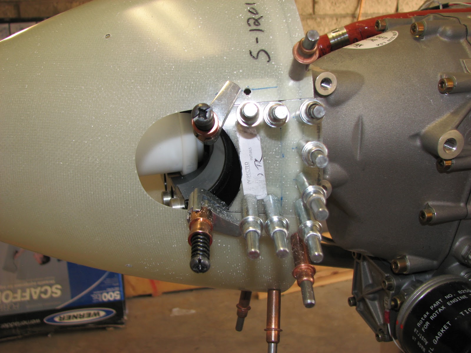
Then the propeller had to get removed to allow for access to the delicate area for installing the gap fillers. The front plate and the front half of the hub were removed and the spinner put back on.
Clamping on the pieces was up next. Note the slight overlap on the back. This is because the cutouts had not been trimmer yet but also to adjust for a reasonable gap to the spinner - taking into account that this will all get painted at some point.


Again, I used the plexiglass bit to start the hole into the fiberglass. It's easy to position and hold it with its very pointy tip.


And then it was final drilled with the #30 bit.


The opposite side when just as well.


The next step startled me at first, because it was requesting a piece of material that I could not recall to have seen before. Well, it was one of the last few unused pieces of metal in a tiny corner on my shelves. 


This one had to get bent to follow the spinners shape (I used the pint can of brake fluid) and then marked to cut off 4 pieces of 1.25" each.


When you do this step, please be smarter than me and put the cut markings on the inside of the curve instead of on the outside as I did. It is much easier to cut with a bandsaw that way.
These pieces had to get attach to the gap filler. Hole measurements marked and drilled.


After drilling, the pieces were ground back to follow the shape of the prop cutouts and then polished smooth. Then the whole assembler was attached to the backplate again and the spinner match-drilled for a #19 hole for the screws that will connect the parts.


Now that all the match-drilling had been done, the last step before removal of the spinner was to final drill all screw holes to #19. This included the front plate that we had removed before when removing the prop blades. And finally everything had to come off. 


And this is not even all that has to come off. The back of the hub as well as the backplate itself will also have to come off to install the nutplates before everything will be installed again.
And just when I was cleaning up and was about to close shop the mail dropped off a package from Van's.


These are the parts for the next Service Bulletin, the one that reinforces the brace for the battery and oil tank. Good timing!
Not that I am looking forward to do this extra job but at least I won't have to wait for parts before I can finish this step.