Showing posts with label Section 46. Show all posts

Sunday, May 19, 2013

Oil Pressure Sensor Mounted

The last step of the Pressure Sensor Relocation was to find a spot on the firewall for attach the Adel clamp and the sensor to.
The hose was not quite long enough to get it all back to the fuel pressure sensor which others used as an attachment point but I found a good route to get it to the GPS antenna shelf.


This position would also allow for a good route without blocking anything important.


and enough clearance at the exhaust if clamped where I put my hand.


Now the only thing missing at the shelf was at least a hole. I decided to install a nutplate as access was easy enough for the squeezer..


That made the installation a one-screw job.


Please note, that I had also installed the clamp at the end of the fire sleeve. On both ends actually.


Crimping on the spade connectors was a routine job but routing the wire for minimum stress and bends was not quite so easy.


Looks like a lot of wire ties but that way the wire is unlikely to break due to vibrations.
This completed the relocation and added another hour to the time balance sheet of this step. Connecting the sensor to the electrical system was the last open step in Section 46 and so I could close that as well.

Next was to catch up with section 49 and install the oil hoses in preparation of the oil cooler installation. But before that, I noticed an interesting schematic in section 46-11 that shows how this fuel distributor block is put together.


This will be interesting in the near future as my engine is one of those that will require the short fuel supply hose from this distributor to the fuel pump to get replaced. This is covered by another SB, but this time issued by Rotax.

With the help of Vielle Burette's pictures posted on his blog, I was able to quickly tackle the question of How-in-the-world-should-I-route-these-oil-hoses question.

I started in reverse order than the instructions ask for as it appeared to be easier that way.


This was the return hose that attaches to the belly of the engine.


By the way, I tried to go below the friction brace too. It appeared that there was less stress on the hose when routed above the brace as shown in the picture.
The next hose was the one attached to the oil pump. Clearance with the fuel spill over pipe was not good and I had to bend the pipe a bit to get the hose to pass it.


I did not do more on this hose and left the support just temporarily attached to the exhaust bolt. This will get completed when I finally hook it up to the oil cooler.
Next was the oil supply hose and that one was the worst to route. I am really grateful that I had a lot of pictures from other blogs to see which way to go. It's really tight behind the engine now.


You can see that I also installed the air filter on this side now. This was because I saw clearance issues with the spill over hose as well as problems to even get the air filter installed at all after the oil hoses were in place. I had to slightly reroute the spill over hose and also routed the oil hoses underneath the fuel supply hose to get a bit more length out of the oil hose.


I had to lift the oil canister up a bit to clear the air filter, so we will see if this is low enough to clear the upper cowl.


This shot was taken from the left side, aiming at the shelf.


Again, from the left side and below so you can see how the hose is resting on the water hoses.


And the final shot that gives you an idea of the clearance between oil cooler and the muffler. This is also the reason why I might have to do this step again. As I had moved my oil cooler about an inch forward of the position Van's had intended, I might now have too short of a hose (on the left side) to connect it to the oil cooler and mount it to the cowl.
It's not a bit deal! If it turns out to be too short I can order a hose, clamps and a longer fire sleeve from Aircraft Spruce and manufacture my own within an hour or less.

Saturday, July 14, 2012

Section 46 Completed

The morning began with cleaning up the mistake I had made last night. The upper engine bolts had no washer under the nuts, so I had to take these off again. No problem as the engine was still supported by the crane.

The nuts sit a little deep and could use a second washer to get the cotter pin more in the usual position. However, the nuts can not turn and so I deem this sufficient with just one washer.

For the lower bolts I needed Elizabeth's help as one person alone can not torque them.

The washers gained a bit of clearance around them after the bolts were torqued to 160-190 inch pounds. We will see if they still touch the mount due to vibration.
That was it. Engine mounted and crane removed.

The fuel hoses were connected next. First the supply at the gascolator.

Then the return line to the shelf fitting.

This had also required to install the VA-216 banjo fitted fuel hose. However, I forgot to take a picture of that. You will see it later when looking at the A/B ignition connectors.
The next step very confusing. Mainly because Van's didn't say that the ominous RV-12 IGNITION HARNESS was not the bunch of wires coming from the panel through the firewall grommet. No, this ignition harness is actually still in a bag and stored in the box of other engine related stuff. Lost some time determining the whereabouts of this harness.

Installing the harness on the A1/B1 ignition plugs was the easy part since they updated the instructions. Dave had experienced some cryptic descriptions that have all been updated on 46-12.

However, the same procedure is done with the Y-split purple wire. And these connectors have to get inserted in the bottom plug of the B2/A2 plugs, which is simply hard to get at at this point. Van's pictures did not show the fuel hose that they had me routed right next to the ignition module earlier. Yes, that would have been easier without that hose in the way.

Finally, I prevailed and got it all back together.

Here are the missing pictures of the banjo fitted fuel hose.

The last pic shows the hook-up to the fuel sensor. What I really wanted to show you though was the crimped on spade connectors on the oil pressure harness. This is the Dynon side of the harness. I did not crimp spades on the wires coming from the Honeywell sensor as I will relocate it. I think it is insane to run this sensor mounted to the engine which is known to rattle the heck out of the sensor sometimes as early as in the first 25 hours. The sensor is priced at $400 and I do not intend to spend this amount of money for a placement mistake.

So I skipped the oil pressure sensor hookup and ran the wires for the CHT sensors and the oil temperature sensors next.

CHT1:
CHT2 and oil temp:

The shielded and folded wire in the following picture is coming from the generator and got connected to the voltage regulator.

Then is got obnoxious. I was supposed to connect the thick wires from the battery to the starter. The positive connection was first and the stud was n a location that was practically unreachable. Even for putting the washer on I needed tweezers.

Van's provided exactly ONE nut to go on that bolt. So I knew I couldn't lose this one. It didn't even come with a size that I could have ordered but was called NUT-00001. No chance I could get that at Ace! What I did to prevent loss of the nut while trying to get it to catch on the bolt was to glue the nut into the hex nut driver with superglue. It worked!

The torque of 35 inch pounds appeared to be a bit loose as it hardly secured the ring terminal but I trust Van's with the number and will keep an eye on it.
The last step of Section 46 was to install the fuel drain for the new style fuel pump. In case of a pump failure this pump will dump the leaking fuel though a fitting to which I was supposed to connect a drain pipe system to.
It started with cutting the hoses and straightening the aluminum tubing.

The tubing has to get flared and then the ends get reduced and radiused to a size that will fit into the hoses but not cut them from the inside. The hose clamps then secure the flared ends inside the hoses. I used the large SB wheel for that job.
My bending skills have degraded a bit since the fuel line installation but they were sufficient to get the job done.

Van's recommended to use safety wire to hold the large clamps together and I can only stress the need for this. As I still don't know how to correctly use the safety wire pliers, I used tie wraps instead. It worked just as well.

Unfortunately, I couldn't convince the drain hose to turn in a way the the bend would face backwards. I left it at full length and didn't trim as I want to see how the cowling can help to hold the hose back. In the event of a pump failure I really want to get the leaking fuel overboard and not spread inside the lower cowling near the hot exhaust and muffler.

That concluded Section 46. Next Tuesday my sensor relocation kit for the Honeywell sender should arrive and then I can finish the section off.

I am not sure what to do next. I am leaning towards following Van's order and work on the prop and spinner but I am wondering if I wouldn't need the engine cowling in a usable shape first.

Friday, July 13, 2012

Engine Mounted

It was along night today. I got home and worked on the preparation for hanging the engine.
I took the carbs off and installed the drip pans.

This is how it looks when the carb is off.

Then I went on to change the configuration of the fuel supply hoses.

The restriction from the upper bolt was removed.

Please note, that though Van's doesn't tell you in the instructions, it is not necessary to completely disassemble the fuel hoses setup. Just take the lower part off and try to keep the parts all together. There won't be any changes to the lower part. The exercise is only to remove the nipple on the top and to turn the clamp block 180 degrees so the hookup point is facing forward.

Leave the allen bolt loose and be patient and eventually the screw of the lower fuel hose assembly will catch and get back into the clamp block.

That was it! Ready to hang the engine. As it was still quite early, I decided to go ahead and drill the holes for the lower engine mount. First I had to remove the tarp and, oh boy, what a nasty surprise I found!

Leaking brake fittings. I don't understand why it took so long to show but as you can see, there's quite some fluid on the floors. As it appears, all of the fittings are leaking, so there's a possibility that the sealant I used is not compatible with the brake fluid. Either way, I will have to drain the brake lines, remove and clean the fittings and try again with BakerSeal. This is quite a setback but I have no choice but to suck it up.
This didn't stop me from continuing to work on the engine though.

I had already installed the AN3 bolts earlier when mounting the nose wheel, so I could move on to drilling and then clamping the drilled side before continuing to drill on the opposite side.

I finished the fuel hose assembly by plugging the upper part and adding torque seal to the lower part.

The lower bolts were put in place.

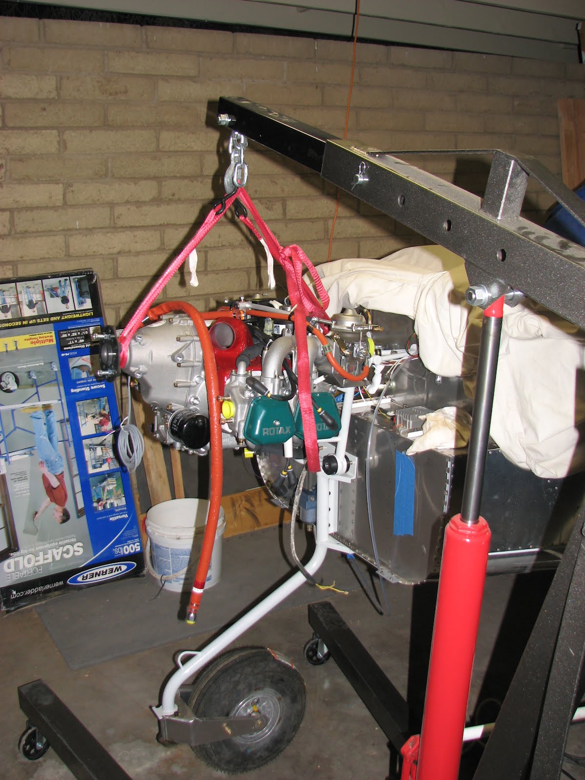
And then it was time for the crane again.

It was indeed quite demanding to fine position the engine and get the dampeners to slide over the bolts. A lot of wiggling and pushing and then it was slowly getting there.

I had started with the lower bolts and later found that the upper bolts appeared to be easier to align. Maybe I should have started on the top.

The only problem that I found where the big washers that cover the dampeners. They are indeed so big that I had trouble installing them when the bolt was in the correct position. Some of them need to get trimmed to allow for clearance with the vibrating and moving engine mount. The clearance you see is before tightening the bolts. I'll have to see if this will be enough or not.

The problem showed mainly with the washers for the lower bolts. Although the upper ones are pretty tight too. I remember reading something about this on VAF when someone found during annual that the mount had indeed touched the washers and the power coating was scraped off due to chafing.
I took a file to it and removed some of the interfering material and then sprayed the exposed steel with primer.

I tightened the upper bolts by feel and the lower ones only hand tight. I ran out of time to finish it, so I let the engine sit for the night, supported by the bolts and the crane.
Tomorrow morning I will torque the bolts and remove the crane and decide what and when to do with the brake fittings.