This year my planning is really completely off. Right when I was getting ready to drill the plexiglass aft window as part of the fitting process of the canopy frame, the temperatures in Tucson dropped significantly. And they stayed low.
I am too afraid to drill the plexiglass at these temps of below 60F and cause cracks, so I am holding off on this step.
Unfortunately, there is not much else I could do right now that would then create a problem or at least some obstacles for the final avionics installation. Even just putting the fuselage on wheels could be something I might regret later when I have to then crawl into the tail cone to install what used to be the magnetometer with the D-180. Without the landing gear attached I can still turn the fuselage on its side and do this job by working from the aft window area.
So, to pass the time until the avionics package is available, I reinvigorated my shooting activities. I got myself a nice Stoeger over/under to see if I like Skeet/Trap and also finished putting together a Remington 700 for some small game hunting.
Still, I can't wait until this SkyView package is ready for me to order!
Thursday, December 22, 2011
Sunday, November 20, 2011
Insert Spiffy Title Here
I was able to pull the whole assembly table with the fuselage on top of it into an area where the roof doesn't cover the patio and so I was able to open the canopy frame far enough to attach the gas struts. That revealed immediately that the frame needed quite some adjustment to fit the fuselage.


The front bow had the common problem of on uneven clearance towards the instrument panel.

And the sides didn't really align flush with the canopy deck parts.


It required quite some wiggling and pushing to adjust the lateral misalignment - but that was nothing to the heart-wrenching pounding with a heavy rubber mallet (the same that shaped the longerons) to get the front bow in uniform distance to the instrument panel. I did not quite achieve the 7/16" and stopped at what looks more like 8/16" or maybe 9/16" but it is the same distance along the whole length of the piece and I didn't want to break it. We'll see how that plays out with the canopy ...
Bit once more I was very impressed with the Stewart paint. All that pounding didn't do anything to the paint. Not a scratch, nothing came off or got dented. Great stuff!


Then it was to adjust the aft part of the frame and this was when I realized that I skipped an important step in the process. In order to align the canopy to the aft window edge, there first has to be an aft window, so it could present an edge to work with!
So I had to interrupt the build here and jump back to section 25 and see how to put that window in. Even more complicated as I chose to use a fuel resistant, tinted window instead of the Makrolon window provided by Van's and this needs a bit more attention.
I got as far as to put the side skirts clecoed back in and noticing that the window needs very careful adjustment before drilling the first hole. Then I ran out of time and had to just let it sit there. Tomorrow I am heading for a short trip to L.A., so I won't be able to finish this step any time soon.


A hand drill is on order from amazon.com as I feel that I don't want to widen those pre-drilled holes in the plexiglass with electric or even pneumatic force.
Saturday, November 19, 2011
Canopy Work Started
Finally back at building and it's fun! After cleaning up the work shop a bit more and making room for the large canopy frame I could more this piece inside the shop and start section 34. A bad time of year to do this as it won't be warm enough to do the fiberglass layup by the time the frame would be ready for it, but I will just have to deal with it, I guess.
First I found out that I had to damage my beautiful paint job that I've done on the frame. The front part of the arched tube had to get filed down where the weld would otherwise have contact with the canopy glass later in the game. Fortunately this won't be a prominent point, so the touch up I will have to do there will likely not show.

Then some countersinking in an unusual size for a #10 screw had to be done on the inside of the frame.

And then some match-drilling, deburring and riveting on both sides of the canopy frame. Sorry for the reflection.

And then the latch handle stop had to get positioned on the frame, then match-drilled, deburred and also riveted. This required a little bit more attention as the part needed some reference lines drawn onto the frame to get correctly positioned. I also installed the handle before match-drilling to make sure there was enough contact surface for the stop to work.

The riveting part was simple as usual.

This was the end of the preparation of the frame. Before installing it on the fuselage I had to find the top cover for the instrument panel area and re-install this cover. Therefore I also clecoed the center piece of the instrument panel in place so the cover would have the correct shape.
The final result looked like this.

Unfortunately, I couldn't install the gas struts yet as I cannot open the frame all the way to get the holes aligned to install the final bolts on each side. The plane will have to get moved from under the patio cover to get that done.
BTW: The Mexican hat in the previous picture is NOT the one that Dave has shown in his blog with the cat dancing on it. The hat certifiably is hanging on this wall for longer than we own the house and never came off. Who knows what we would find on the inside? I rather not find out!
Thursday, November 10, 2011
Paint Booth Removed
It took me two half days to get the paint booth removed from the car port. Building it was actually faster :-)


Now on to building some more....


Now on to building some more....
Wednesday, October 12, 2011
Tank Painted
I'm late with updating this entry but the work has been done as anticipated. Yesterday I painted the last parts for the interior, the map box, the fuel neck and the tank.
Despite my troubles in getting a good job done when priming (remember, I produced some small runs), the paint job turned out way better than my previous average work. Actually I think the map box and the tank are my masterpieces with the spray gun.
Take a look at the pieces and note the shiny reflections which prove that the surface is really smooth. Here are the parts right after applying the last coat.


And here after a night of polymerizing in the heated paint booth.

I believe, I am done with painting large interior parts at this point but before tearing down the paint booth I will do an inventory and see if there's nothing hiding in a corner of the shop ...
Sunday, October 9, 2011
Back to Building
Finally! After quite a long hiatus I am back at building. Not with full motivation yet but at least I AM doing something with the plane. Main reason why I am not really gun-ho about it yet is that the still-not-availability of the aviation package is frustrating. I refuse to accept the idea that I would have to crawl back into the tailcone to install the magnetometer thingy and some wires and tubes, lying on my back, resting on two fragile little bulkhead webs. Installing this stuff right now when I can still turn the fuse on its side would be hell of a lot easier and so I am currently hoping (or call it: dreaming) that this aviation package is going to be available before I put the fuse on wheels....
So, I am back at building. What did I do? The tank needed paint and the first step is to prep the aluminum - usually. With the tank there's an earlier step. This is to remove the gunky spillover from sealing the tank with Pro-Seal. This is particularly ugly at the fuel window which I left open (I know I will likely regret this). So I had to find a technique to remove this stuff without damaging the window. Van's calls for building a tool from a wooden spatula with a sharp tip. I did tha but also used a scalpel to cut loose thick chunks before going at them with the wooden tool.

This shows me somewhat into the job (a few holes on the left side have been cleaned up).

This is after being done, also showing the two tools used.
The edges of the tank were trimmed with a loose razor blade. Careful! Don't cut yourself.
Then the tank was up for the usual surface prep and drying in the sun. My painting skills suffered a bit during this hiatus as I didn't show the usual patience putting on the multiple coats and giving the, enough time to dry before the next one was put on. The result? Runs! This is not so bad with this primer as it's to sand. This better not happen during the paint run!!!
BTW: The window holes can be covered with self adhesive felt patches. The diameter should be 3/8" which makes them fit perfectly in the holes.


I only primed the left and right side (the right more accidentally than willingly, call it a mistake), the top and the front of the tank. Only these sides will be exposed and there's no need for paint on the other sides. This way the tank will be paintable in one long run instead of needing multiple days to be able to put it on a previously painted side.
The primer should fully dry over night and then tomorrow I will probably sand and paint.
I also primed the fuel neck and the map box.


Tuesday, August 16, 2011
Houston, we are leak-free!
I finally took a plunge testing the fuel tank for leaks. I was very afraid of a negative result as I felt overwhelmed by just thinking about taking this gooped up box apart and doing this all over again. I seriously thought about selling the project in case the tank turned out to be leaky.
Well, I don't have to worry about it for now as it turned out to be totally gas tight, I used a more sensitive pressure gauge for that test as Van's was warning about testing the tank with pressures beyond 1 psi. I tested it with 8 inches of water, which is about a 1/3 psi. It actually later turned out that the tank was so gas tight that the pressure rose up to 12" as I had filled it with cool air from the shop A/C and the system warmed up over night and therefore increased the pressure.
Initially the tank leaked somewhat but it turned out to be leaking around the fuel neck flange and the Moeller gauge hole which I had covered up with a plate. After tightening the screws on these flanges the tank did not lose any air in 12 hours.

I hooked up the pressure gauge to the fuel outlet of the tank and plugged the return line inlet. The rest as per plans in addition to covering the hole for the Moeller gauge.
Saturday, July 23, 2011
Alive and Well
Yes, I am still here. Didn't do much building on the RV-12 recently though. Part of this is owed to selling my little grasshopper which is supposed to allow to purchase an Engine Kit if I decide to stay on the ELSA track.
This sale got finalized on Friday when I received the funds and the plane was flown to Southern California where the new owner took it over to spend some vacation and then fly it up to its new home in Washington state.
Now, that this is done and I don't have the worries of how to finance my RV-12 anymore, I should be back at building the next days = despite the still active monsoons.
Wednesday, July 13, 2011
Catching Up With Controls
After closing up the fuel tank and still waiting for the sealant to fully cure, I caught up with the installation of the control elements.
The first step was to trim the blocks that would hold down the flap handle.

Before installing the flap handle I realized that going further back in the tunnel to install the flaperon pushrods the still installed turtle deck skins would make access unnecessarily hard, so I removed them.

Back to installing the flap handle. It turned out that it was easier to install the flap handle and the flaperon mixer at the same time as they are connected.

I noticed that the sticks were not quite aligned and straight after connecting everything to the mixer. The right stick appeared to be ok but the pilot side was pointing outboards when supposed to be in straight and level flight. I even sat in there to verify that this wasn't an optical illusion. I had measured the pushrods and set them according to the plans. I decided to adjust this a little as I didn't like the look of it. This took quite some time but I ended with 3 full turns longer than I had the pushrod measured before. The whole adjustment process was a bit awkward and mostly guess work, because the sticks move when the flap handle is actuated. It must be coming from the radial movement of the mixer which is supposed to the a linear one. I wonder how this will feel in flight. Here's a better shot of the flaperon mixer.

Installing all this took around an hour as accessibility was close to ridiculous with the fuselage on its belly. I decided to turn the fuse on its side for the next steps. With the tail cone attached, it is significantly harder to turn the fuselage on its side but it's still manageable.
When I wanted to slide the flaperon pushrods into the tunnel I realized I had made a building mistake. The roll servo was already installed and torqued into place which prevented me from getting those dang long pushrods into the tunnel. The only possible access point is through that cutout in the back of the cockpit floor that was blocked by the servo. I removed it, cussed because of those two forward bolts that are hardly accessible and slid the pushrods in without any problem.

I put the servo back in place and cussed a bit more (about the same bolts as before). Here's a picture of the rear tunnel with the pushrods installed.

Finally I installed the powder-coated Flaperon Torque Arms and connected them temporarily to the pushrods. They will get match drilled a little later and then removed again to get match drilled on the opposite side which you can't reach with the arms installed in the plane.
Once this was all connected I was amazed how mushy and wobbly the whole control track felt. I think it mostly caused by the torque arms not having a stable pivoting point. They can literally move all 3 dimensions and so they try to avoid to go in the direction you want to go in. I expect this to go away when their counterparts are installed and the wings are connected as they will provide lateral stability for the bearing of the torque arms.

Here's a view of the whole installation area.

I just hope I don't have to take anything of this out again - ever. I am completely aware that by saying this I have doomed myself to eventually having to just do that - taking it all out again. It will probably be because of a fuel leak which I overlooked despite all the pressure testing ... Can you tell I'm in a positive mood today?
Monday, July 11, 2011
Fuel Tank Closed Up
Today was the day. Let's just hope I don't have to do this again!

Two things I did, deviating from the plans, I should mention. First, the order of the final assembly.
I had the front plate uninstalled when getting to this final step. First I riveted the clips to the top, gooping them up as necessary.
Then I put a thick layer of sealant in the corners to seal off the top when it comes on. Use a finger to spread it well but leave it thick, don't spread it out too much. Don't forget to put lots of goop on the inside where the tank has this little bent. The cutouts in that bend have to be well covered with sealant.
Then I installed the top skin. Don't worry about the clips just yet. Focus on aligning the skin without losing too much of the goop. Once sparsely clecoed, reach inside the tank through the front plate and snap the clips onto the return line. Mine felt a little loose so I added a cherry sized amount of sealant to them. Just goop it on a finger and feel your way with one of the clean ones.
After riveting the top skin on, I riveted the filler neck on, then finally going for the front plate and then installing the fuel sender.
This all took exactly two hours after mixing which happens to be the pot life of my Chemseal stuff.
The second thing I changed is quite obvious in the picture. It's the added ground wire, directly attached to one of the screws that holds the sender in place. I felt that with multiple layers of ProSeal the ground would have a hard time getting propagated over those plates. Installing a wire is much simpler and more reliable. I will run the other end to the forward inboard mounting screw.
Sunday, July 10, 2011
Selling a Plane for an Engine
This week was quite an exhausting one. Not because of countless hours in the shop but because of readying my little grasshopper for sale. It is currently undergoing a pre-sale inspection and will be hangared thereafter to protect from this year's violent summer storms. If the inspection doesn't reveal any yet undiscovered problems with the engine the sale should got through this month.
Although I haven't built this little gem and just owned a few months short of two years, I have built up quite some pleasant memories during this time and while flying it into the controlled airspace of the strip where the inspection would take place, I relived all these great memories. It was a challenging task to perform a greaser landing while being distracted of the realization that this might very well be the last time landing this beautiful plane.
Once we have done the paperwork next week, I should have my answer as to how to pay for the RV-12 engine kit and also a revitalized and strong desire to finish the build at hand.


Wednesday, July 6, 2011
Monsoons Stopped Building
The last two days I came home to find that the electricity had been cut off and they didn't repair it until late in the night. So, no light in the shop, no A/C, no internet. I didn't get to start the last chapter on the fuel tank therefore and it might not be the last chapter anyway if I find a leak.
Let's hope those monsoons decide to dump their load in another part of town for the next days so I get to finish this task.
Let's hope those monsoons decide to dump their load in another part of town for the next days so I get to finish this task.
Sunday, July 3, 2011
Fuel Tank Ready for Final Step
The last few days I was on and off working on the plane, mostly in the shop. It wasn't really worth posting every little step of progress so I am summarizing the last days in one post today.
On Thursday, I manufactured the clips that will hold the fuel return line to the top skin of the tank. It would have been an easy job had Van's provided the material. I thought I had seen a strip of aluminum for this purpose but as much as I was browsing and searching the list of contents for the bags, I could not find it. A part that small must be either in the bags or was a leftover from a larger part where most of it was used elsewhere, alas I could not remember where I would have put such a left over. Either way, I had no material and studying the drawing I thought I scrounge up some skin pieces from the scrap bin. I did so and cut and bent the piece to shape and created some beautiful clamps - only to find that I had overlooked the material thickness laid out in the drawing. It said .032 and I had used ordinary .025 from a skin. So back to the scrap bin and retrieving some .032 parts this time. This is a rare good but after a while I found a suitable piece and went through the manufacturing process once again.

Then I manufactured the return line inside the tank. I cut the tube to length, allowing for a lot of excess material (final cut can happen once installed). Flaring one end was simple and I installed it on the fitting. Making those bends inside the tank was not really hard to do and it helped determining the correct position for the bend by eye-balling the height from the side of the tank.
After the first bend I put on the top skin with a few clecos to determine where I had to make the upward bend to guide the line into the filler tube.

I marked the position this time (pretty close to the cutout as the bend takes a half the diameter of the opening), removed the skin and bent the tube. Then I put the skin back on and also put the flange in position to determine how much of the tube I had to cut off.

I cut off the tube and deburred the end, then removed the top skin.

That was the result of Thursday. I had also tried to rivet in the ring for the Moeller gauge but this attempt failed miserably. It turned out that I had no good flat surface that was also strong enough to not dent when hammered and allow the skin to rest evenly at the same time. I ordered a steel plate at Amazon to try again.
The steel plate arrived on Saturday and that's when I went back at it. With a little effort I was able to get those countersunk rivets set without pushing them out in the process. I held the nutplates in place with their respective screw after alliging the rivet holes with clecos.

As the final installation will be done with Pro-Seal it doesn't matter if the rivets are really completely flat with the surface.
This is how the inside of the tank will look like.

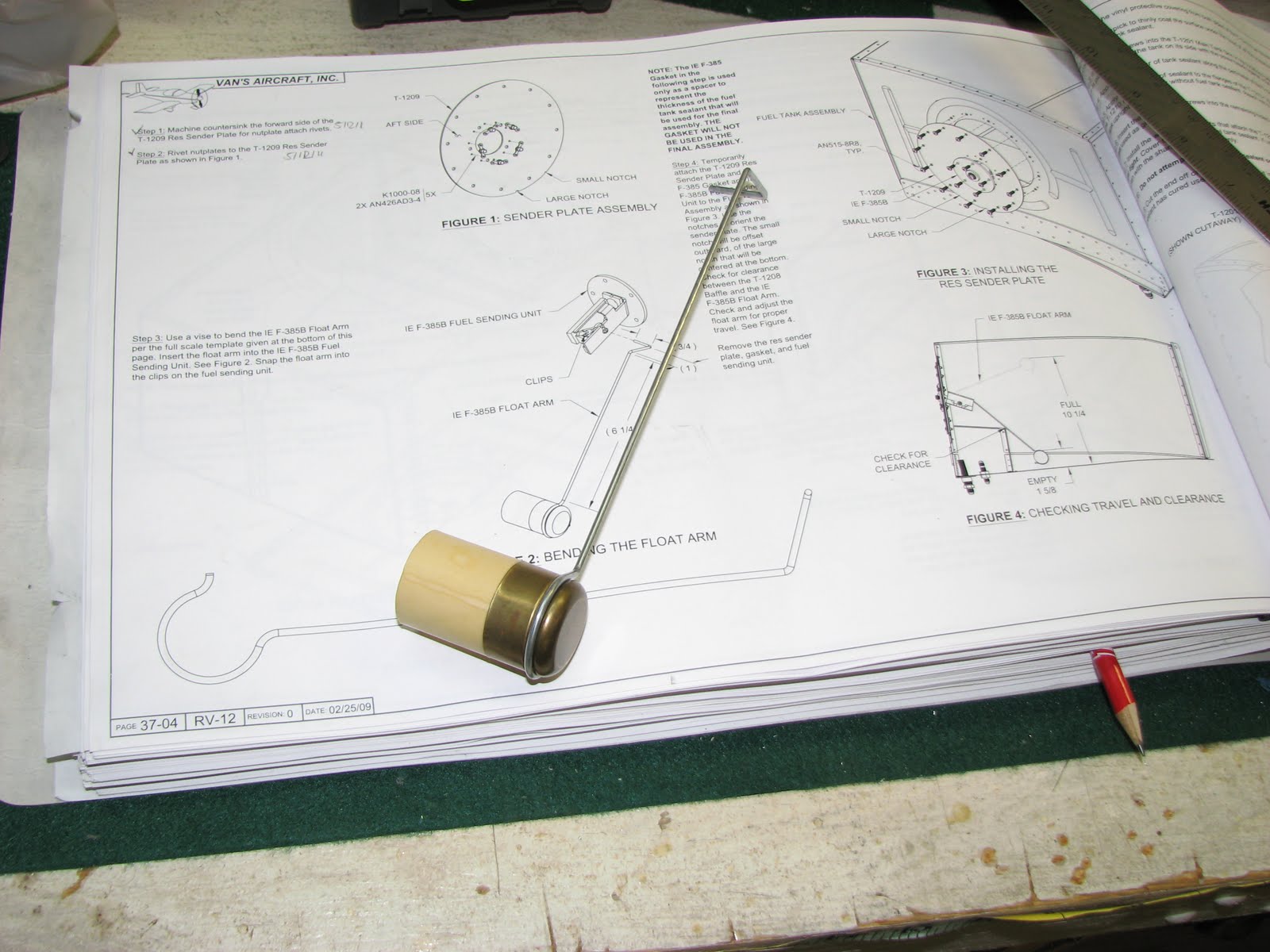
On Sunday, today, I finished the tank work by pre-installing the fuel sender and scuffing up the flanges that will get prosealed and riveted next. Bending the steel wire to plans was easy with a vice and a hammer - but, hey, I have a lot of experience since the flaperons when it comes to banging the cr*p out metal!


That done, I had to verify that the sender arm wouldn't contact the cross baffle, so I installed the sender for a trial fit.


As you can see the baffle was not an issue. I could easily put my finger in between the baffle and the wire without lifting the floater. I also measured the arm movement and I came quite close to the values listed in the instructions. In lowest positions the top of the floater is 1 5/8" above the tank bottom. At the highest position this measures 10 3/4", 1/2" more than in the instructions.
Then I went on and made two candles as Dave called them. If you're unfamiliar with Dave's recent blog entry, he was talking about the flaperon push tubes.
After cutting, deburring and truing the cut of the tubes, I marked the center of the holes to drill with blue tape. I have some aluminum brackets to hold pipes in a vise which came in very handy now.

I drilled the hole through the tube so it exited in the other side to reduce the number of alignments (and curses) I had to do. To make sure that the second set of holes would be close to be "evenly spaced" with the first set, I used this little trick (look at the head of the bolt):

The result looked like this.

I prepped and primed the parts and riveted them together (make sure mark them before taking them apart so you know which stub goes into which end of which tube!) and adjusted them for correct length.

The tank is now ready to get its finally internal cleaning and then I can goop the parts together and pray that the pressure test after it fully cured will show that it is indeed not leaking. I might be doing this tomorrow morning ...
On Thursday, I manufactured the clips that will hold the fuel return line to the top skin of the tank. It would have been an easy job had Van's provided the material. I thought I had seen a strip of aluminum for this purpose but as much as I was browsing and searching the list of contents for the bags, I could not find it. A part that small must be either in the bags or was a leftover from a larger part where most of it was used elsewhere, alas I could not remember where I would have put such a left over. Either way, I had no material and studying the drawing I thought I scrounge up some skin pieces from the scrap bin. I did so and cut and bent the piece to shape and created some beautiful clamps - only to find that I had overlooked the material thickness laid out in the drawing. It said .032 and I had used ordinary .025 from a skin. So back to the scrap bin and retrieving some .032 parts this time. This is a rare good but after a while I found a suitable piece and went through the manufacturing process once again.

Then I manufactured the return line inside the tank. I cut the tube to length, allowing for a lot of excess material (final cut can happen once installed). Flaring one end was simple and I installed it on the fitting. Making those bends inside the tank was not really hard to do and it helped determining the correct position for the bend by eye-balling the height from the side of the tank.
After the first bend I put on the top skin with a few clecos to determine where I had to make the upward bend to guide the line into the filler tube.

I marked the position this time (pretty close to the cutout as the bend takes a half the diameter of the opening), removed the skin and bent the tube. Then I put the skin back on and also put the flange in position to determine how much of the tube I had to cut off.

I cut off the tube and deburred the end, then removed the top skin.

That was the result of Thursday. I had also tried to rivet in the ring for the Moeller gauge but this attempt failed miserably. It turned out that I had no good flat surface that was also strong enough to not dent when hammered and allow the skin to rest evenly at the same time. I ordered a steel plate at Amazon to try again.
The steel plate arrived on Saturday and that's when I went back at it. With a little effort I was able to get those countersunk rivets set without pushing them out in the process. I held the nutplates in place with their respective screw after alliging the rivet holes with clecos.

As the final installation will be done with Pro-Seal it doesn't matter if the rivets are really completely flat with the surface.
This is how the inside of the tank will look like.

On Sunday, today, I finished the tank work by pre-installing the fuel sender and scuffing up the flanges that will get prosealed and riveted next. Bending the steel wire to plans was easy with a vice and a hammer - but, hey, I have a lot of experience since the flaperons when it comes to banging the cr*p out metal!


That done, I had to verify that the sender arm wouldn't contact the cross baffle, so I installed the sender for a trial fit.


As you can see the baffle was not an issue. I could easily put my finger in between the baffle and the wire without lifting the floater. I also measured the arm movement and I came quite close to the values listed in the instructions. In lowest positions the top of the floater is 1 5/8" above the tank bottom. At the highest position this measures 10 3/4", 1/2" more than in the instructions.
Then I went on and made two candles as Dave called them. If you're unfamiliar with Dave's recent blog entry, he was talking about the flaperon push tubes.
After cutting, deburring and truing the cut of the tubes, I marked the center of the holes to drill with blue tape. I have some aluminum brackets to hold pipes in a vise which came in very handy now.

I drilled the hole through the tube so it exited in the other side to reduce the number of alignments (and curses) I had to do. To make sure that the second set of holes would be close to be "evenly spaced" with the first set, I used this little trick (look at the head of the bolt):

The result looked like this.

I prepped and primed the parts and riveted them together (make sure mark them before taking them apart so you know which stub goes into which end of which tube!) and adjusted them for correct length.

The tank is now ready to get its finally internal cleaning and then I can goop the parts together and pray that the pressure test after it fully cured will show that it is indeed not leaking. I might be doing this tomorrow morning ...
Subscribe to:
Posts (Atom)

