Not following the flow Van's has laid out for us really costs some extra penalty in time. Tonight is a good example for this rule. I wanted to jump ahead and fit the control sticks before continuing the wiring which would have required to run the microphone switch wire up the control stick. After this you wouldn't want to remove the hole setup anymore, so I rather do the final install first and then run the wire.
That started out well. I filed down the brass bushings to fit inside the control column bracket. Then I reduced the length of the guide rod on the end of the control stick where this bushing will sit in so it would just clear the bracket.
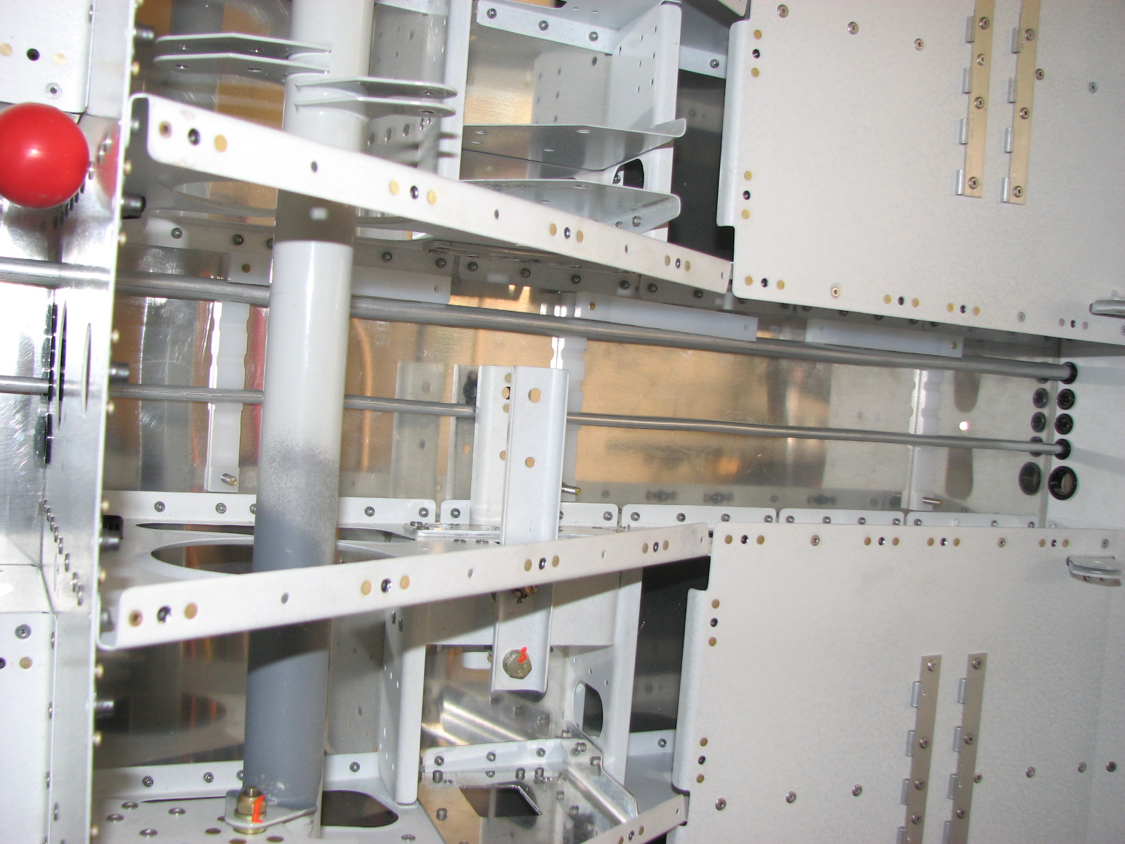
But when I wanted to install the whole setup to see if my attempt on the left side was correct, I noticed that installing the roll pushrods after installing the control stick might be a very tricky thing to do as the space around the bottom of the stick is very limited.
I thought about this a moment and then decided to do it right the first time and roll back to the beginning of the whole control stick installation and make those aileron pushrods first, so I could install them along with the control stick.
So then I was working my way through section 32 in reverse. In the end nothing got finished therefore. The pushrods got cut and pre-drilled as well as tapped. Now they are sitting outside and drying the primer I sprayed on.
The left control stick is still lying in the fuselage waiting to get installed to verify that the bracket is holding onto the brass bushing and not touching the guide rod in the stick.
But any progress is still progress, right?
By the way, I still have a leak somewhere in the fuel system. Last night I ran a test after noticing that I am still losing pressure over night by putting 11 psi in the system and shutting the fuel valve. I wanted to find out if the leak is possibly in the suspicious hose connecting supply and return line.
Well, when I came home tonight and checked the pressure was down to 6 psi. Opening the valve dropped it even further down to 2.5 psi. So I have a leak in front and behind the fuel valve. Oh boy! I still know that it's water tight to 10 psi, so I am willing to take a chance with fuel. I will put rags under the possible leaks and put just a small amount in the system to begin with. Maybe pressurizing it again to simulate operating pressure.
But this will have to wait until I am in a better mood to deal with this.
Tomorrow, I'll wrap the stuff up and get it ready to get shipped to Dave in Ohio who wanted to borrow the set for his test.
Showing posts with label Section 28. Show all posts
Showing posts with label Section 28. Show all posts
Tuesday, June 7, 2011

Friday, June 3, 2011
Main Wire Harness Installed
On Thursday night I didn't post although I found the time to do some preparatory work for the wire installation. Nothing major, so I didn't care to do an extra post for that. Just verified that the counter plates for the wing wire contacts have the right side and do not interfere with the side skins, so I riveted them to those triangular metal frames and put them away for now. With the fuselage on the side all the time they shouldn't be on anyway.
I also got a replacement pressure gauge as my previous one stopped working either because water got in it or because I slightly overpressured it accidentally for half a second or so. Anyway, it didn't want to reset to 0 anymore and all the readings seemed to be pretty weird. I installed the new one that now goes up to 30 psi (as a precaution) and I connected the return line with a hose to the main supply line. It's now pressurized to 9.5 psi and still holding. I will let it sit over night to see if this is it. I sure hope so.
Today I started the wiring part of section 31 and this looked pretty shocking.

Fortunately for me I soon found out that I missed one snap bushing when routing the main harness and so I got another chance of making this look decent and preventing mistakes.

While I was pulling back the out the harness from my previous mistake I taped the bundle together every foot and so the harness became more like one long, thick cable and much more hand-able.
When I put those fans I could help myself but smile about that note that says that you shouldn't over tighten the screws as you could break off the edges of the fan. Well, 25 years ago when I was playing with electronics a lot and building PCBs and such, it was well known that you don't use a long screw on such fans without a bearing in between the edges to prevent this bending from happening. Nothing fancy, just a piece of plastic tube cut to length. I had a feeling that I still had some of that in of my sorters and sure enough I found just the right amount to make four of those tubes. If you look closely you can see them in the picture.

The first connection had to be made. This is hooking up the wires with the fuel flow sensor. Mine is an FT-60 as in all newer models.

Then the rest of the harness was to be run through the tunnel. Now it looks much more cleaned up.

Take a closer look at the conduit in the center section. I ran the 3 strings through it as described in the manual. But instead of running a new string every time I run a wire through there I just closed the string and made a loop out of it. That way I won't lose a string and can run wire after wire with it. Worked well so far.

Finally, when I got to the point of installing those pesky reed relays I decided to just pull the parts and prepare them but not to start this tricky installation when I'm tired. That is certainly a job for the morning when I have more patience.

And then, just before closing shop, I took a photo of the pressure gause to remind me in the morning what it read last night. A bit fuzzy, probably too close.

I also got a replacement pressure gauge as my previous one stopped working either because water got in it or because I slightly overpressured it accidentally for half a second or so. Anyway, it didn't want to reset to 0 anymore and all the readings seemed to be pretty weird. I installed the new one that now goes up to 30 psi (as a precaution) and I connected the return line with a hose to the main supply line. It's now pressurized to 9.5 psi and still holding. I will let it sit over night to see if this is it. I sure hope so.
Today I started the wiring part of section 31 and this looked pretty shocking.

Fortunately for me I soon found out that I missed one snap bushing when routing the main harness and so I got another chance of making this look decent and preventing mistakes.

While I was pulling back the out the harness from my previous mistake I taped the bundle together every foot and so the harness became more like one long, thick cable and much more hand-able.
When I put those fans I could help myself but smile about that note that says that you shouldn't over tighten the screws as you could break off the edges of the fan. Well, 25 years ago when I was playing with electronics a lot and building PCBs and such, it was well known that you don't use a long screw on such fans without a bearing in between the edges to prevent this bending from happening. Nothing fancy, just a piece of plastic tube cut to length. I had a feeling that I still had some of that in of my sorters and sure enough I found just the right amount to make four of those tubes. If you look closely you can see them in the picture.

The first connection had to be made. This is hooking up the wires with the fuel flow sensor. Mine is an FT-60 as in all newer models.

Then the rest of the harness was to be run through the tunnel. Now it looks much more cleaned up.

Take a closer look at the conduit in the center section. I ran the 3 strings through it as described in the manual. But instead of running a new string every time I run a wire through there I just closed the string and made a loop out of it. That way I won't lose a string and can run wire after wire with it. Worked well so far.

Finally, when I got to the point of installing those pesky reed relays I decided to just pull the parts and prepare them but not to start this tricky installation when I'm tired. That is certainly a job for the morning when I have more patience.

And then, just before closing shop, I took a photo of the pressure gause to remind me in the morning what it read last night. A bit fuzzy, probably too close.

Monday, May 30, 2011
Canopy Painting Completed
After proving yesterday that the fuel lines are liquid proof I focused on finishing the painting of the canopy parts this morning. We had a refreshingly cool day that was perfect for painting and I made good use of it. Within 3 hours (some parts needed their opposite side painted as well) I finished sanding, cleaning and painting of all the parts.
All that's left to get interior paint now is related to the fuel tank. I keep the paint booth for a little longer to see if I can at least paint the base cube in it to improve the paint job.

After painting I checked the temperature to be 80 degrees, exactly what we had last night when I last checked the pressure in my fluid filled test.

The pressure reading is exactly what it should have been. I drained the system as good as I could without turning the fuse on its belly again. I will try to hook up the return line and find a better matching hose for the two different fitting sizes or try to widen the clear hose under heat to make it slide of the bigger fitting of the supply line. I am not too worried about the return line through as the problems I had were all related to the NPT side of the fittings and the return line doesn't have any of these.
I guess I will start with the wiring now and leave the fuselage on its side for that.
All that's left to get interior paint now is related to the fuel tank. I keep the paint booth for a little longer to see if I can at least paint the base cube in it to improve the paint job.

After painting I checked the temperature to be 80 degrees, exactly what we had last night when I last checked the pressure in my fluid filled test.

The pressure reading is exactly what it should have been. I drained the system as good as I could without turning the fuse on its belly again. I will try to hook up the return line and find a better matching hose for the two different fitting sizes or try to widen the clear hose under heat to make it slide of the bigger fitting of the supply line. I am not too worried about the return line through as the problems I had were all related to the NPT side of the fittings and the return line doesn't have any of these.
I guess I will start with the wiring now and leave the fuselage on its side for that.
Sunday, May 29, 2011
Second Leak Fixed
The day started with spraying the white primer for the paint coat on the last stack of parts before the fuel tank. That was quickly done and the parts were left for drying.

Warning from the future!
Here I am traveling back in time from 2.5 years after I created this easter-egg to warn you NOT to follow my steps in how I tested the fuel system for leaks. While I was successful in finding and eliminating the leaks this way, I also created a serious problem in the fuel system that could have caused quite some more pain than it did in my case (which was luck alone!).
The water in the system will cause the fuel pump to rust and decrease its performance significantly (or make it fail). This will lead to low fuel pressure issues on long WOT runs and will require a fuel pump replacement to fix (I am not sure if also the transducer might have been damaged by the water).
My suggestion is to use air alone at this point and to ensure that the temperature is the same when comparing PSI values from over-night runs. The alternative is to use actual gas but do recommend against it as it is too dangerous to mess with gas when there is a safer option.
Then it was back to the pressure test. The thread sealant should have had enough time over night to cure enough to withstand a few pounds.... I set everything back up again and set the pressure to around 7 psi. It didn't show an immediate drop so I let it alone and installed the servos for the autopilot.

That was kind of awkward to install first I thought I had to break my hand to get the servo in position with the pushrod already installed, then getting at the hex nuts to screw the servo in place was hard too. My hand seems a bit on the large side compared to the average Oregonian. I finally got all in only to realize I had forgotten to put the Loctite on. Argh! All out and back in. The second time was easier it appeared. Either my hand shrunk or I got used to the tight space. Anyway, I think installing the pushrod on the servo arm AFTER the servo has been installed would have been easier.
Back to checking the pressure.
Ouch!
It dropped half a pound while I was installing servo one. What the hell is this?
I pulled my soap water gun out and threatened those fittings but it didn't help. The leak must be a small one and hard to see with soap water. I used the flooding method and finally found another fitting that built up a foam collar although much slower and less impressive as the one I found yesterday. This time it was the forward fitting on the fuel valve. I drilled out the rivets holding the valve assembly to better work on it, removed the fitting and cleaned the threads as well as I could. Washed everything off with alcohol and smothered it with Rectorseal No.7 and put it back in. I gave it about 15 minutes to cure as I felt like I really had it with this cr*p. I pressure tested the valve assembly while still on the work bench and confirmed it was good to operating pressure of the fuel pump (about 5 psi). The difference was that I must have been worried about stripping the threads last time I put it in. Only the first 5 threads where in the valve and now I've screwed it almost completely in.
I put it back in the line but didn't want to give it my usual 8 psi test yet as the sealant was all fresh and I didn't want to blow it out with too early of a test. So I worked on the second servo.

(Comment from the past: You see this roll servo neatly installed at this point. DO NOT DO THIS! This is too early as it will prevent you from inserting the very long flaperon pushrods through that opening in the aft bulkhead that is blocked by the servo. Wait with this step until the pushrods are in place.)
Much easier to install although I don't know how to torque the forward two nuts. There's no way you can put a socket on them AND get a torque wrench connected to it. I torqued by feel instead.
Back to the pressure test. I filled the system with 8 psi and waited a little. I noticed a very small but noticeable drop.
Jeeeez!
What else can I do? Oh, I know! No more air! I need a liquid to see were it drips. I decided to hook up a small pump I have to fill the system with water (while the pump is on you have to push the gascolator drain to allow the air to escape).

Once the system is filled with water, I squeezed the water hose to stop the back bleeding and the I could add water through the Schrader valve to set it to the pressure desired. My gauge, Schrader valve assembly is above the water line, so this is the only part of the system that is not flooded.

Back to 8 psi again and waiting.
I went in the paint booth to check the parts and they were dry enough to get sanded with SB pads. So that's how I spent the waiting time, getting the parts ready for painting.
After half an hour I checked the gauge again.

I grabbed the work light and checked for leaks in the tunnel. Everything was perfectly dry. Not even moisture.
I sprayed the parts above the water line with soap again and couldn't see a blip. I checked the drain valve, not even moisture.
At this point I was considering selling the project.
Breath, Breath, Think!
I checked the water hose.

And there it was! A few drops of water were coming out of the large hose and resting on the clear line. As you can see I had a diameter issue here and no converters. This hose-in-a-hose thing with a clamp was all I could come up with. And that's were it leaked.
I clamped it a bit more and in different places and finally saw the bleeding stop and the pressure staying where it was.
Now the only unanswered question is: Why does it work with water but not with air? It looked like I had a very slow drop before doing the water test and I didn't have that hose hooked up then. I had a plug sitting on that end instead.
So was this test successful? Hm, I don't want fuel leaking into my plane. If I'd be flying with water I think I'd be good now. Unfortunately, that's not the case, is it?

Warning from the future!
Here I am traveling back in time from 2.5 years after I created this easter-egg to warn you NOT to follow my steps in how I tested the fuel system for leaks. While I was successful in finding and eliminating the leaks this way, I also created a serious problem in the fuel system that could have caused quite some more pain than it did in my case (which was luck alone!).
The water in the system will cause the fuel pump to rust and decrease its performance significantly (or make it fail). This will lead to low fuel pressure issues on long WOT runs and will require a fuel pump replacement to fix (I am not sure if also the transducer might have been damaged by the water).
My suggestion is to use air alone at this point and to ensure that the temperature is the same when comparing PSI values from over-night runs. The alternative is to use actual gas but do recommend against it as it is too dangerous to mess with gas when there is a safer option.
Then it was back to the pressure test. The thread sealant should have had enough time over night to cure enough to withstand a few pounds.... I set everything back up again and set the pressure to around 7 psi. It didn't show an immediate drop so I let it alone and installed the servos for the autopilot.

That was kind of awkward to install first I thought I had to break my hand to get the servo in position with the pushrod already installed, then getting at the hex nuts to screw the servo in place was hard too. My hand seems a bit on the large side compared to the average Oregonian. I finally got all in only to realize I had forgotten to put the Loctite on. Argh! All out and back in. The second time was easier it appeared. Either my hand shrunk or I got used to the tight space. Anyway, I think installing the pushrod on the servo arm AFTER the servo has been installed would have been easier.
Back to checking the pressure.
Ouch!
It dropped half a pound while I was installing servo one. What the hell is this?
I pulled my soap water gun out and threatened those fittings but it didn't help. The leak must be a small one and hard to see with soap water. I used the flooding method and finally found another fitting that built up a foam collar although much slower and less impressive as the one I found yesterday. This time it was the forward fitting on the fuel valve. I drilled out the rivets holding the valve assembly to better work on it, removed the fitting and cleaned the threads as well as I could. Washed everything off with alcohol and smothered it with Rectorseal No.7 and put it back in. I gave it about 15 minutes to cure as I felt like I really had it with this cr*p. I pressure tested the valve assembly while still on the work bench and confirmed it was good to operating pressure of the fuel pump (about 5 psi). The difference was that I must have been worried about stripping the threads last time I put it in. Only the first 5 threads where in the valve and now I've screwed it almost completely in.
I put it back in the line but didn't want to give it my usual 8 psi test yet as the sealant was all fresh and I didn't want to blow it out with too early of a test. So I worked on the second servo.

(Comment from the past: You see this roll servo neatly installed at this point. DO NOT DO THIS! This is too early as it will prevent you from inserting the very long flaperon pushrods through that opening in the aft bulkhead that is blocked by the servo. Wait with this step until the pushrods are in place.)
Much easier to install although I don't know how to torque the forward two nuts. There's no way you can put a socket on them AND get a torque wrench connected to it. I torqued by feel instead.
Back to the pressure test. I filled the system with 8 psi and waited a little. I noticed a very small but noticeable drop.
Jeeeez!
What else can I do? Oh, I know! No more air! I need a liquid to see were it drips. I decided to hook up a small pump I have to fill the system with water (while the pump is on you have to push the gascolator drain to allow the air to escape).

Once the system is filled with water, I squeezed the water hose to stop the back bleeding and the I could add water through the Schrader valve to set it to the pressure desired. My gauge, Schrader valve assembly is above the water line, so this is the only part of the system that is not flooded.

Back to 8 psi again and waiting.
I went in the paint booth to check the parts and they were dry enough to get sanded with SB pads. So that's how I spent the waiting time, getting the parts ready for painting.
After half an hour I checked the gauge again.

I grabbed the work light and checked for leaks in the tunnel. Everything was perfectly dry. Not even moisture.
I sprayed the parts above the water line with soap again and couldn't see a blip. I checked the drain valve, not even moisture.
At this point I was considering selling the project.
Breath, Breath, Think!
I checked the water hose.

And there it was! A few drops of water were coming out of the large hose and resting on the clear line. As you can see I had a diameter issue here and no converters. This hose-in-a-hose thing with a clamp was all I could come up with. And that's were it leaked.
I clamped it a bit more and in different places and finally saw the bleeding stop and the pressure staying where it was.
Now the only unanswered question is: Why does it work with water but not with air? It looked like I had a very slow drop before doing the water test and I didn't have that hose hooked up then. I had a plug sitting on that end instead.
So was this test successful? Hm, I don't want fuel leaking into my plane. If I'd be flying with water I think I'd be good now. Unfortunately, that's not the case, is it?
Saturday, May 28, 2011
Pressure Test Failed
I didn't get up as early as I had wanted to and so the early morning priming session had to wait. Just as well, as I had later found out that I hadn't really prepared all the parts correctly yet.
I started in the shop by cleaning and scuffing the parts I had missed and setting up the paint both to accommodate the large canopy frame, allowing me to walk around it when painting.

These are some of the parts that will get painted.
When this was all done the friendly USPS postman came by and dropped off the parts I had waited for from Aircraft Spruce to get the pressure test done. So, I quickly pulled the tarp off of the fuselage and set up the fittings to connect return and supply line at the tank area to pressure test the whole fuel line at once.
Oops, that didn't work out at all. The pressure I put in with a ball pump didn't even hold for a few seconds. And I was wondering if I could really hear a hissing sound or if this is a sign of developing a tinnitus... Well my ears are ok. It turned out the ball pump is so cheap it wouldn't hold pressure slowly leaking air unless you kept on pumping.
I removed the ball pump and hooked up the tire filler gauge to the compressor.
Ah, that was better!
Oh, wait, wasn't this 0.1 psi higher a moment ago?
Sure was!
So there was a leak! At least one, I should say ...
I used the fuel valve to shut off everything behind it but I till lost pressure. That could have meant that either the valve is leaking, or the leak is in front of the valve, or the valve doesn't perfectly shut off.
I first wanted to make sure my test setup was leaky itself, so I removed and tested the pressure gauge and Schrader valve assembly. It turned out to be perfectly sealed.
I didn't trust the valve and started removing flared tube connections one by one. Cleaning them, greasing them with fuel lube and putting them back on. Still a leak.
When I got to the valve I decided to stop and see if I can locate the leak with soapy water as I was starting to believe the valve did indeed cut off the aft line.
After cleaning the whole forward tunnel with soapy water I finally sprayed it on the fitting end of the aft connection of the fuel flow sensor. Aha! That's how a bubble bath in the making looks like. It was leaking not at the flared end but where the fitting screws into the sensor.
I removed the fitting, cleaned the threads as good as I could and put a thick layer of Rectorseal No. 7 on it and screw it back in. While I was doing that I was thinking that this could have all been easily avoided by getting the pressure test equipment before even starting on the fuel lines. That way I could have tested every component before putting it into the plane. Now I'm thinking about pressure testing the brake system before putting fluid in it as well!
I assumed that an immediate follow-up pressure test could jeopardize the seal and so I decided to stop there and let the sealant cure before I add pressure to the system again.
I went back to prep and prime and finished the priming part. I decided that the steel parts as well as the parts that get into contact with the elements should get primed green as that stuff is the better corrosion primer. This would include the flap handle, the flap guide assembly and the canopy and the canopy skirts.

After some two hours the stuff had turned green.

Somewhere in between, I forgot when, I also primed the servo pushrods. Because of that dreaded fuel line leak I didn't get to the installation of the servos today.

I started in the shop by cleaning and scuffing the parts I had missed and setting up the paint both to accommodate the large canopy frame, allowing me to walk around it when painting.

These are some of the parts that will get painted.
When this was all done the friendly USPS postman came by and dropped off the parts I had waited for from Aircraft Spruce to get the pressure test done. So, I quickly pulled the tarp off of the fuselage and set up the fittings to connect return and supply line at the tank area to pressure test the whole fuel line at once.
Oops, that didn't work out at all. The pressure I put in with a ball pump didn't even hold for a few seconds. And I was wondering if I could really hear a hissing sound or if this is a sign of developing a tinnitus... Well my ears are ok. It turned out the ball pump is so cheap it wouldn't hold pressure slowly leaking air unless you kept on pumping.
I removed the ball pump and hooked up the tire filler gauge to the compressor.
Ah, that was better!
Oh, wait, wasn't this 0.1 psi higher a moment ago?
Sure was!
So there was a leak! At least one, I should say ...
I used the fuel valve to shut off everything behind it but I till lost pressure. That could have meant that either the valve is leaking, or the leak is in front of the valve, or the valve doesn't perfectly shut off.
I first wanted to make sure my test setup was leaky itself, so I removed and tested the pressure gauge and Schrader valve assembly. It turned out to be perfectly sealed.
I didn't trust the valve and started removing flared tube connections one by one. Cleaning them, greasing them with fuel lube and putting them back on. Still a leak.
When I got to the valve I decided to stop and see if I can locate the leak with soapy water as I was starting to believe the valve did indeed cut off the aft line.
After cleaning the whole forward tunnel with soapy water I finally sprayed it on the fitting end of the aft connection of the fuel flow sensor. Aha! That's how a bubble bath in the making looks like. It was leaking not at the flared end but where the fitting screws into the sensor.
I removed the fitting, cleaned the threads as good as I could and put a thick layer of Rectorseal No. 7 on it and screw it back in. While I was doing that I was thinking that this could have all been easily avoided by getting the pressure test equipment before even starting on the fuel lines. That way I could have tested every component before putting it into the plane. Now I'm thinking about pressure testing the brake system before putting fluid in it as well!
I assumed that an immediate follow-up pressure test could jeopardize the seal and so I decided to stop there and let the sealant cure before I add pressure to the system again.
I went back to prep and prime and finished the priming part. I decided that the steel parts as well as the parts that get into contact with the elements should get primed green as that stuff is the better corrosion primer. This would include the flap handle, the flap guide assembly and the canopy and the canopy skirts.

After some two hours the stuff had turned green.

Somewhere in between, I forgot when, I also primed the servo pushrods. Because of that dreaded fuel line leak I didn't get to the installation of the servos today.

Wednesday, May 25, 2011
Bakersealed
I just wanted to give a short update on the fuel pressure test that I wanted to perform yesterday. Well, it turned out that for one, I wouldn't have had to wait a day for the Bakerseal to dry as it wasn't at all dried after 24 hours. I assume that is supposed to stay that way and so I encourage you to just wipe excess amounts off as they'd end up on your fingers anyway if you don't
So I went ahead and flared the short pipe extension to connect the brass tee to the gascolator fuel supply nipple. That went well and also putting the cap on the return line nipple on the firewall. Unfortunately I then had to discover that my memory had fooled me on the hook-ups to the tank. There I wanted to attach a hose of some kind to short the return with the supply line and run a pressure test over both lines at the same time. Now, the ends of these tubes are flare and need fittings to allow a hose to connect and I hadn't ordered those fittings.
Grmbl!
So I put in another order with Aircraft Spruce in the faint hope of getting these parts before the long Memorial Day weekend. I used economy USPS First Class shipping so chances are I might get it on Saturday, as California is right around the corner.
So I went ahead and flared the short pipe extension to connect the brass tee to the gascolator fuel supply nipple. That went well and also putting the cap on the return line nipple on the firewall. Unfortunately I then had to discover that my memory had fooled me on the hook-ups to the tank. There I wanted to attach a hose of some kind to short the return with the supply line and run a pressure test over both lines at the same time. Now, the ends of these tubes are flare and need fittings to allow a hose to connect and I hadn't ordered those fittings.
Grmbl!
So I put in another order with Aircraft Spruce in the faint hope of getting these parts before the long Memorial Day weekend. I used economy USPS First Class shipping so chances are I might get it on Saturday, as California is right around the corner.
Monday, May 23, 2011
Short Session
I just had an hour tonight to work in the shop. I assembled the pressure gauge with a tee and the Schrader valve and the fluid fitting that will connect the assembly to the gascolator. I used Bakerseal on the threads, so it will take a day to dry enough to withstand pressure. I probably can finish flaring the pipe for the gascolator connection tomorrow and setup the test pressure then.

And then I had a moment to rivet together the parts that comprise the flap handle base. I want to paint this once it's assembled and not the separate parts as it is easier that way.

Some countersinking had to be done here so the base would stand straight on a flat surface.

And then I had a moment to rivet together the parts that comprise the flap handle base. I want to paint this once it's assembled and not the separate parts as it is easier that way.

Some countersinking had to be done here so the base would stand straight on a flat surface.
Fuel Line Pressure Test Coming Up
I spent the weekend with some light work of pulling and deburring the last parts for painting. Almost all were related to the canopy and the flap handle. I think I'll have two more paint sessions coming up. One with the canopy and flap handle parts and one for the fuel tank and related parts. Then I could tear the paint booth down and make room for the full length fuselage, so I'd have a place to store and work on the fuselage after the tailcone got attached.
Today I should receive the last parts to set up a pressure test for the already installed fuel lines, leaving out the tank. I'm a bit paranoid about fuel leaks in the plane but I guess this is a healthy attitude. The missing part is the Schrader valve and it is supposed to be in the mail when I get home. I have to manufacture a short piece of flared aluminum tubing connection but other than that I have it all in stock now. Hopefully I can set up the test tonight and have it sit over night to get a full 24 hour test done by tomorrow evening.
If this turns out to be good, I would start with the wiring.
By the way, I am now close to 700 hours of build time. including all the priming I decided to do. According to Van's build estimate I should be about done by now, which is realistic if I hadn't primed.
Today I should receive the last parts to set up a pressure test for the already installed fuel lines, leaving out the tank. I'm a bit paranoid about fuel leaks in the plane but I guess this is a healthy attitude. The missing part is the Schrader valve and it is supposed to be in the mail when I get home. I have to manufacture a short piece of flared aluminum tubing connection but other than that I have it all in stock now. Hopefully I can set up the test tonight and have it sit over night to get a full 24 hour test done by tomorrow evening.
If this turns out to be good, I would start with the wiring.
By the way, I am now close to 700 hours of build time. including all the priming I decided to do. According to Van's build estimate I should be about done by now, which is realistic if I hadn't primed.
Saturday, March 5, 2011
Section 28 Completed
Friday night and Saturday morning I worked on completing the installation of the fuel system. Only the forward return line had to be done to accomplish this, but it happened to be the line that needed the experience from all the previous sections to get successfully completed.
It started with the artsy bending of the forward vertical section that will pick up the fuel at the firewall shelf and run it down into the tunnel. Therefore it needed a 90 degree bend to become horizontal as well as an offset bend to get to where the cushioned clamp is after passing the fuel transducer of the supply line.

To allow for small length adjustments while getting the flared end attached to the fitting I have learned that an S bend can be very helpful. So I added that right at the upper end of the line.

It turned out to be a good idea to do an aggressive S bend here as the upper part was way too long with the 14.5" requested by the instructions. While adjusting I needed to put some masking tape on the lower 90 degree bend to avoid scratching the primer off the skin. Feeding the long horizontal end of the tube into the tunnel was another story. watch the tube when it's sliding under the flaperon mixer as it wants to scratch and scrape on it (not good for neither one).

Once in place make sure that you press the tubing down underneath the mixer to allow for full uninterrupted travel.

When you have attached the forward end to the fitting temporarily you can then work on cutting off the tube on the other end and flare the end for the bulkhead fitting that you had hopefully installed before you put the belly skin on. Otherwise I am expressing my deepest condolences at this point.
Do not forget to put the nut and the sleeve on on this one! There's not enough tubing left if you do.

This concluded the activities on Friday night. This morning I finished the installation. Free hand bending the forward part to accommodate for the fact that I had cut off the tube too short - although I had the feeling it would be long and already anticipating adding some free hand S bends to shorten it.
Getting the screw into this cushioned clamp took me about 30 minutes! This was partly owed to the fact that it took me 8 minutes to determine that the hole was not large enough to let the screw pass into the nutplate. First I thought this K1000-3 was another mishap where I installed a -08 but this wasn't the case. I used a counter sinking tool to widen the hole enough to let the screw pass. The rest of the time was owed to the line being a tad too short.

From there it runs into the tunnel and passes the fuel valve...

then under the mixer and through the front of the bulkhead.

Here it then attaches to the bulkhead fitting. The only access to this area is through the belly access hole.

While I was tightening the nut on the fitting I noticed that although I thought I had tightened the fitting very well, it did move with the nut. Darn it! Fortunately my wife was here to help me and hold the wrench on the opposite side so I could tighten nut and fitting.
With my wife present at the time I was done with this I quickly ran the last section of my blow pressure test and found the return line to be good.
Section 28 took me just short of 16 hours, 15.75 hours to be precise, including the learning curve on how to bend and flare tubing.
It started with the artsy bending of the forward vertical section that will pick up the fuel at the firewall shelf and run it down into the tunnel. Therefore it needed a 90 degree bend to become horizontal as well as an offset bend to get to where the cushioned clamp is after passing the fuel transducer of the supply line.

To allow for small length adjustments while getting the flared end attached to the fitting I have learned that an S bend can be very helpful. So I added that right at the upper end of the line.

It turned out to be a good idea to do an aggressive S bend here as the upper part was way too long with the 14.5" requested by the instructions. While adjusting I needed to put some masking tape on the lower 90 degree bend to avoid scratching the primer off the skin. Feeding the long horizontal end of the tube into the tunnel was another story. watch the tube when it's sliding under the flaperon mixer as it wants to scratch and scrape on it (not good for neither one).

Once in place make sure that you press the tubing down underneath the mixer to allow for full uninterrupted travel.

When you have attached the forward end to the fitting temporarily you can then work on cutting off the tube on the other end and flare the end for the bulkhead fitting that you had hopefully installed before you put the belly skin on. Otherwise I am expressing my deepest condolences at this point.
Do not forget to put the nut and the sleeve on on this one! There's not enough tubing left if you do.

This concluded the activities on Friday night. This morning I finished the installation. Free hand bending the forward part to accommodate for the fact that I had cut off the tube too short - although I had the feeling it would be long and already anticipating adding some free hand S bends to shorten it.
Getting the screw into this cushioned clamp took me about 30 minutes! This was partly owed to the fact that it took me 8 minutes to determine that the hole was not large enough to let the screw pass into the nutplate. First I thought this K1000-3 was another mishap where I installed a -08 but this wasn't the case. I used a counter sinking tool to widen the hole enough to let the screw pass. The rest of the time was owed to the line being a tad too short.

From there it runs into the tunnel and passes the fuel valve...

then under the mixer and through the front of the bulkhead.
Here it then attaches to the bulkhead fitting. The only access to this area is through the belly access hole.

While I was tightening the nut on the fitting I noticed that although I thought I had tightened the fitting very well, it did move with the nut. Darn it! Fortunately my wife was here to help me and hold the wrench on the opposite side so I could tighten nut and fitting.
With my wife present at the time I was done with this I quickly ran the last section of my blow pressure test and found the return line to be good.
Section 28 took me just short of 16 hours, 15.75 hours to be precise, including the learning curve on how to bend and flare tubing.
Wednesday, March 2, 2011
Aft Fuel Return Line Installed
I had started the endeavor on the Fuel Return Lines a day ago but stalled and didn't really have to report any noticeable progress after 2 hours of cutting, bending and flaring. The reason was that although I followed the plans meticulously and my bends were nearly perfect, I had forgotten that following the plans in this particular case was not a good idea as I had deviated from them before as my bender didn't allow to put a bend so close to the end of a tube as the Van's bender does when I fabricated the fuel supply line. Now the return line was supposed to get bent to follow the route of the supply line closely so they could get attached to each other. By following the plans I produced a really nice piece of aluminum scrap tubing.

You can see both tubes together in this picture. The right one I did a day ago when I noticed that this won't really work out and it also was too short as due to my deviated bend I needed a little more tubing that Van's had measured. The left one is the one I partly improvised tonight. There is one bend missing in this photo which will get the tube to the bulkhead fitting. This bend and the flare was done after verifying that this time everything fit and matched the idea of the plans.

I didn't get a chance to check if the fitting is air tight but this will be done tomorrow when my wife can lend me a hand, um, better a finger to cover the fitting on the other side of the bulkhead.
Last step was then to install the chafing buffers which seem to be made from a thick fuel hose and held in place by (quite heavy) stainless steal clamps. It's a bit tricky to get to the clamps to tighten them but fortunately the sides are still open at this time and the lightening holes are big enough to get your arm through them.


Taken from the right side of the fuselage.

Again from the right side, showing the overlap of the two tubings.

And finally the distance of the two tubings at the tank mounting point. At this point this is pretty much just an educated guess but the fine tuning should be easy as the 1/4" tubing can be bent by hand easily.

You can see both tubes together in this picture. The right one I did a day ago when I noticed that this won't really work out and it also was too short as due to my deviated bend I needed a little more tubing that Van's had measured. The left one is the one I partly improvised tonight. There is one bend missing in this photo which will get the tube to the bulkhead fitting. This bend and the flare was done after verifying that this time everything fit and matched the idea of the plans.

I didn't get a chance to check if the fitting is air tight but this will be done tomorrow when my wife can lend me a hand, um, better a finger to cover the fitting on the other side of the bulkhead.
Last step was then to install the chafing buffers which seem to be made from a thick fuel hose and held in place by (quite heavy) stainless steal clamps. It's a bit tricky to get to the clamps to tighten them but fortunately the sides are still open at this time and the lightening holes are big enough to get your arm through them.


Taken from the right side of the fuselage.

Again from the right side, showing the overlap of the two tubings.

And finally the distance of the two tubings at the tank mounting point. At this point this is pretty much just an educated guess but the fine tuning should be easy as the 1/4" tubing can be bent by hand easily.
Sunday, February 27, 2011
Main Fuel Lines Installed
I extended the existing main fuel line (as opposed to the return line) from the fuel forward to the fuel valve. This is the first tricky fuel line as you start on the work bench but then when a few bends have been added, you have to install the straight line through the snap bushing and finish the flare on the plane as you wouldn't be able to get the flared line through the bushing.

This line is actually really long. It runs through the tunnel between the bulkhead that supports the wings passed the mixer and though the forward bulkhead that supports the seats. That's the area where you have enough room to put the final flare on. Don't worry about bending the tubing upwards as the radius is very wide and will easily get removed afterwards.

The ability to pull the line back a bit and bend it upwards to have a little room to finish the flare (do not forget to put nut and sleeve on before you do or the line has to be cut and removed!) is the reason why this last bulkhead hole right before the valve has been widened and has no snap bushing to guide the line.

The fact that you can shut off a valve was very helpful when I did my blow test after tightening down those nuts on the flares.
The next steps were preparation for more tube bending. I needed to install the connection points for these tubes. So, the gascolator and the transducer (fuel flow detector) got their fittings and plugs installed. A word of caution about the hole in the firewall that should allow for the fitting to screw into the mounted gascolator. I had widened this hole and remove the flange that covered that hole early on before riveting the lower firewall to the fuselage. I used an actual fitting to check that there was enough room. My assumption was that there was nothing for me to do or even check when I screwed the gascolator in place. This was wrong. And this was worsened by the fact that it needs quite some time to screw those AN3 bolts in and out on the gascolator as they are not easy to get at. You need a simple wrench and you can't move it more than a quarter of a turn before resetting it. So, when you do this, just screw in the bolts hand tight to get an alignment. push the gascolator to the firewall and verify that you can screw the fitting into it from inside the firewall. I used a Dremel to widen the hole a bit on the lower side. It turned out that the gascolator sat a little too low and therefore was off center with the fitting hole in the firewall That's was caused the problem.


While the thread sealant on those fittings got some time to set, I continued working on the tubings that would eventually connect them. First the short transducer/gascolator tube got bend and flared.

This one was easy as it could get finished on the work bench, so on to the longer one that runs from the valve to the transducer. This one I had to bend completely but leave the final flare off as it would have to get pushed through a snap bushing again.

Notice the little S bend on the left side that doesn't have the nut installed yet? This is particular for the FT-60 transducer that I have. Apparently there are two different transducers used in RV-12s and the FT-60 needs an additional offset bend to get the tube a bit higher to where the fittings sit. This adjustment was holding a surprise for me at this point.
So I pushed the unflared end through the bushing, attach the flared end to the valve to get the adjustment and length right and then I noticed the surprise...

The line looks absolutely perfect. Follow it from the valve through the bushing up to the transducer. Can you see the surprise there?

Yeah, right! This offset didn't get me to the fitting, did it? Sure the tube is too long but that's part of the exercise here as I was to mark the correct length in this step too. Now, as the tube is not where it was supposed to be I first had to take care of that. The distance to the fitting is almost two pipe diameters. Out with the tube, creative free hand bending (with the help of the bending tool), some cursing, in though the bushing, some more manual fine adjustments, marking the correct length, and out again, cutting and deburring of the cut end and back in again, some more cursing about the confined space to operate the flaring tool, double checking that the nut and sleeve are on and flared. Whew! After this fast forward I saw this:

A much better fit although the line looks a little abused. Not a biggy though as it will be covered by the tunnel covers. Only you and I know about it ... ;-)

Compared to this back-and-forth action the final installation of the line between the transducer and the gascolator was a piece of cake. I took care to cut the tubing as long as Van's requested in the instruction. However, the gascolator line appeared to be a bit short. It turns out that this could easily corrected by pulling the S bend apart a bit to allow for a perfect seat on the fittings.

I blow-pressure tested the line up to the valve. After that I needed a second person to seal the open end and there's was no one else around. So, I have to do this when I wife gets back from San Diego tomorrow.
The fuel supply lines are done. The next step is to provide the fuel return line.

This line is actually really long. It runs through the tunnel between the bulkhead that supports the wings passed the mixer and though the forward bulkhead that supports the seats. That's the area where you have enough room to put the final flare on. Don't worry about bending the tubing upwards as the radius is very wide and will easily get removed afterwards.

The ability to pull the line back a bit and bend it upwards to have a little room to finish the flare (do not forget to put nut and sleeve on before you do or the line has to be cut and removed!) is the reason why this last bulkhead hole right before the valve has been widened and has no snap bushing to guide the line.

The fact that you can shut off a valve was very helpful when I did my blow test after tightening down those nuts on the flares.
The next steps were preparation for more tube bending. I needed to install the connection points for these tubes. So, the gascolator and the transducer (fuel flow detector) got their fittings and plugs installed. A word of caution about the hole in the firewall that should allow for the fitting to screw into the mounted gascolator. I had widened this hole and remove the flange that covered that hole early on before riveting the lower firewall to the fuselage. I used an actual fitting to check that there was enough room. My assumption was that there was nothing for me to do or even check when I screwed the gascolator in place. This was wrong. And this was worsened by the fact that it needs quite some time to screw those AN3 bolts in and out on the gascolator as they are not easy to get at. You need a simple wrench and you can't move it more than a quarter of a turn before resetting it. So, when you do this, just screw in the bolts hand tight to get an alignment. push the gascolator to the firewall and verify that you can screw the fitting into it from inside the firewall. I used a Dremel to widen the hole a bit on the lower side. It turned out that the gascolator sat a little too low and therefore was off center with the fitting hole in the firewall That's was caused the problem.


While the thread sealant on those fittings got some time to set, I continued working on the tubings that would eventually connect them. First the short transducer/gascolator tube got bend and flared.

This one was easy as it could get finished on the work bench, so on to the longer one that runs from the valve to the transducer. This one I had to bend completely but leave the final flare off as it would have to get pushed through a snap bushing again.

Notice the little S bend on the left side that doesn't have the nut installed yet? This is particular for the FT-60 transducer that I have. Apparently there are two different transducers used in RV-12s and the FT-60 needs an additional offset bend to get the tube a bit higher to where the fittings sit. This adjustment was holding a surprise for me at this point.
So I pushed the unflared end through the bushing, attach the flared end to the valve to get the adjustment and length right and then I noticed the surprise...

The line looks absolutely perfect. Follow it from the valve through the bushing up to the transducer. Can you see the surprise there?

Yeah, right! This offset didn't get me to the fitting, did it? Sure the tube is too long but that's part of the exercise here as I was to mark the correct length in this step too. Now, as the tube is not where it was supposed to be I first had to take care of that. The distance to the fitting is almost two pipe diameters. Out with the tube, creative free hand bending (with the help of the bending tool), some cursing, in though the bushing, some more manual fine adjustments, marking the correct length, and out again, cutting and deburring of the cut end and back in again, some more cursing about the confined space to operate the flaring tool, double checking that the nut and sleeve are on and flared. Whew! After this fast forward I saw this:

A much better fit although the line looks a little abused. Not a biggy though as it will be covered by the tunnel covers. Only you and I know about it ... ;-)

Compared to this back-and-forth action the final installation of the line between the transducer and the gascolator was a piece of cake. I took care to cut the tubing as long as Van's requested in the instruction. However, the gascolator line appeared to be a bit short. It turns out that this could easily corrected by pulling the S bend apart a bit to allow for a perfect seat on the fittings.

I blow-pressure tested the line up to the valve. After that I needed a second person to seal the open end and there's was no one else around. So, I have to do this when I wife gets back from San Diego tomorrow.
The fuel supply lines are done. The next step is to provide the fuel return line.
Subscribe to:
Posts (Atom)

