Saturday, January 28, 2012

All Wheels Assembled

On Friday the package from Harbor Freight arrived and I received the tools I needed to finish the wheel assemblies. The main problem was that the local HF store is stocked worse and worse and this time they were out of long hex bits and the necessary adapters to match the 3/8" drive to the 1/4" drive the torque wrench expects.
So back in the shop and torquing those wheel bolts.


Then I had to "pack" those bearings with grease. Never done anything like it before, so I had ordered a tool to reduce the messiness of the job.


The messiest part of which was filling it with the automotive bearing grease that I had ordered with it.
All I had to do to pack the bearings was put it in the tool and push a handle down for a while until grease was pouring out of it on the top. You can see the covered tool behind the almost finished main wheel #1.


The last step was to reassemble the brake.


That finished wheel #1 and I took a little break before working on #2 but I found out later that the new hex bit drivers also helped a lot with the disassembly of the rim and so I was a bit amazed that the whole work on wheel #2 summed up to just one hour from start of disassembly to finish.


And that finished the first page of the Main Gear section. This is how guys that are half way down to 90 years old celebrate their birthday, or at least I did it like that.
I sure am happy to see that the first avionics packages can finally be ordered for the guys that are stuck and waiting more desperately than I do yet. This gives me hope that I can now just go on building and soon be able to finish the avionics section to get back to an efficient building rhythm.

Sunday, January 22, 2012

One Main Wheel ... Almost ... Assembled

The front wheel was pretty easy to do but those main wheels sure looked intimidating to me.
I decided to take one step after the other and began by taking of the two screws that held the brake assembly to the wheel. The main axle had to be taken out as well to get the assembly off but pulling that preinstalled cotter pin out was something. You have to pull it out as far as it would let you and then start bending it a little, pull a little more then bend a little more and so until it finally comes out. Removing the nut and pulling the axle then is a piece of cake.


The next step is to remove the brake rotor. Easy to do by removing 3 screws.


Then turn the rim over and remove the 6 nuts. 3 nuts do not need the bolt to be support from the other side. Those 3 are the ones that also protrude through the hub. You'll see later why that is. Splitting the rim needs a little wiggling with the help of a flat screwdriver. Help the rim to come apart step by step. It can take a bit as the fit is really tight.


The 3 bolts you had to support while taking the nuts off are the ones that should come out easily. I noticed that the bolts didn't have washer under their heads. All of the nuts did.
Now's a good time to remove those bearings. Mine were completely dry, so no need to remove any grease.


Those last 3 bolts have to get unscrewed from the hub. YES, the hub is tapped and the bolts are screwed into the hub and then countered with the nuts you had removed earlier. That's why there was no need to support these bolts while unscrewing the nuts.


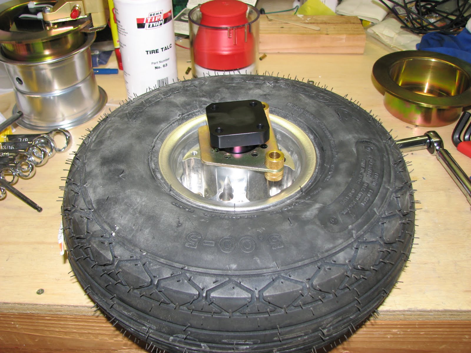
These bolts will be tricky to torque correctly when reassembling the wheel. I ordered a 1/4" hex driver with a 3/8" shaft to attach to my torque wrench but I'll have to wait until it gets here.
Taking the hub out (yes, you'll have to although you might not believe it now. Try to push the valve stem through the rim and you'll see that the rim of the hub prevents this from happening) is easily done with a wooden hammer or something similarly light. Then it's on to put the tube on the rim.
You'll might want to do it right, I know I did, and put the valve stem washer and the valve nut on the valve stem to hold it firmly in the center of the hole in the rim. I tried every trick in the book, I even thinned the washer down to half the thickness...


... but to no avail. Even when I got the not on the whole assembly to just catch on the first thread, I couldn't tighten it or pull on the valve stem from inside without pulling the nut off. There was just no way to get the washer on.
I decided just put the nut on (with the rounded edges facing the rim) and tighten it slightly to hold the valve stem in the center and hope for the best. I read others did the same thing and were fine.


After "solving" this problem, I put the hub back in and screwed the bolts back in, not finally torqued because of the missing tool. You'll have to tighten the valve nut correctly and align the nut to allow the hub to pass it, so you won't have a chance to tighten a valve nut that is too loose when you inflate the tire. The hub won't allow the nut to turn. I just hope I found the right amount of torque without pulling the valve out of the tube...
Then it was on to dusting the tube with talc and stuff it into the tire and mounting the other half of the rim back on. A piece of advise on the tire talc before you do this task: The reason it's so hard to get talc these days is because this stuff is almost as bad for your lungs as asbestos. So don't breathe it in. Not now and not later, which means don't do the dusting in the work shop. Although you might see my talc can sitting on the work bench I actually went outside behind the shop and did the job there while wearing a light respirator. And I put the wheel on the work bench carefully only for the photos. The work in between was done outside in the car port.


And then finally putting the other bolts and nuts back in that hold the rim together.


This is where I stopped as I don't have the right tools to tighten the hub bolts before putting the nuts on. The whole ordeal with the first main wheel took around 2 hours. I am sure that know that I understand how it is supposed to work the second one will take more around 30 minutes.

Thursday, January 19, 2012

Front Tire Assembled

Tonight I repaired the rear window by gluing back in the two pieces that had broken off the window when opening the attach holes. I didn't touch it since I glued it in to not disturb it and I'll check tomorrow if it worked out well. The photo didn't turn out so well as I had put transparent tape over it to hold it in place and the reflection makes it a bit hard to see through it.


Then I followed the instructions of 35-02 and split the front wheel rim.


The drawing on 35-02 shows washers under the nuts and the bolt heads holding together the rim but mine didn't have any washers, there were only bolts and nuts coming out.

After locating the tube I had a really hard time to figure out if the special valve shoulder washer and the valve nut would have to hold the tube to the rim somehow. After a lot of browsing through other blogs I found the solution on the Matco website. To save you some time, here's the answer: Leave the valve nut and the valve washer alone, tighten the nut maybe but the assembly stays as it is. The outer nut right under the cap should get removed as I read the plans and it doesn't appear to serve any purpose if you left it in place anyway.
So after finally locating the answer to the tube installation, it was on to applying (way too much) tire talc and squeeze that tube into the tire.


Then I had to slowly inflate and then deflate the tire and repeat the process a few times while squeezing and massaging the deflated tire in between to make sure the tube was wrinkle-free inside.
Finally I inflated it to roughly 28 psi as instructed and put the assembled tire aside.


That ended my evening in the shop. Next it's on to the more tricky main tires.

Monday, January 16, 2012

Main Gear Section Started

The first step in Section 35 has nothing to do with the main gear or any gear at all. It deals with installing the upper engine mount and that immediately revealed a severe lack of proper tools.
After drilling the holes into the firewall and the engine mount blocks and deburring the holes, I noticed that I neither had a torque wrench that would allow for a torque of the 160-190 inch pounds, nor did I have the proper adapter to connect the 3/8" nut to the 1/4" torque wrench. This stalled my day in the shop that I had planned for.
A quick look on amazon showed that there was a good torque wrench available that would deliver the necessary torque as well as provide the desired 3/8" connection. I ordered it right away but it wouldn't get here before Wednesday.
I couldn't motivate myself beyond getting this step started and didn't feel the desire to start working on the actual tires.

Sunday, January 15, 2012

A Little Bit of This, a Little Bit of That

I finished the rear window installation by tapping the match-drilled holes in the rollbar with a 6-32 drill tap. There's really not a lot of material holding the screws in the rollbar, and the screw is certainly harder than the aluminum, so I better remember not to tighten them too much when installing the window.
I have not yet repaired the crack I caused in the rear window but I received the cement necessary to do so.
Instead I started pulling the parts for the Main Gear section to start assembling the tires. It also looks like installing the upper part of the engine mount would be a possible step to complete next.
In a surge of overwhelming optimism I also checked the Van's website to see if there was an updated Avionics order form available as rumor had it that it should be available around now. Did it really surprise me that it still said that they are working on the SkyView update and that they wouldn't take any orders for now?

Saturday, January 7, 2012

Rear Window Done

So I received my clecos on Friday just in time to get some work done over the weekend. Thank you , Avery!

I finished the match-drillling and accomplished a pretty good fit to the rollbar. Not perfect as I wanted to - there's a slight skew over the width of the window which I probably can compensate for when fitting the canopy.


This is how it looks from the inside.


Then I took everything apart and finished the task by opening up the holes in the rollbar and in the rear window. That's when it happened. I honestly despise drilling plexiglass! I already learned this fact when working on the landing light cover. Then at least it was a few holes that were controllable. Not so with the rear window! One of the last holes opened caught on the material and it cracked and broke out a part of the forward flange. I think I'll be able to glue it back in and make it look ok. It's on the top, so not too visible and certainly not a stability issue.
Anyway, when you get to this task, be super careful about the opening part and apply almost no pressure at all with the plexi drill.
I didn't take a photo of that boo-boo but I will do that when I have the cement to fix it.

Now, I am thinking to do some prep work on the Main Gear section as the temps are down again and doing epoxy work is probably not a good idea at this time.

Monday, January 2, 2012

Rear Window Installation

Finally it was warm enough (sounds like we were due, huh? No, we're really lucky this year to get a warm spring-like weather just around New Year's - it was at 78F today!! God, I can so see the envy in your face :-) ).
I didn't feel like finding excuses to not work on the plane any longer and so I just removed the tarp from the fuselage and started fitting the rear window. Remember, I ordered the plexiglass version of the rear window which is provided by Carl Eldridge and is fuel resistant and mine is also tinted to reduce the heat in the cockpit and of the fuel a bit. The Lexan version Van's provides is pre-drilled so you can cleco the window to the rear and side skins before match-drilling the front to the rollbar. Well, it's not that easy with the plexiglass version. First it is not pre-drilled so you will have to align it by yourself as well as stabilize it during the first holes drilled.
Furthermore, there is a section in the center rear that interfere with some brackets on the inside of the cockpit and the window has to get trimmed to clear these brackets. Not too much though to leave enough beef for the screws to hold the window onto the sheet metal.


This shows the right side bracket in question. See the little cut out that allows the window to pass the bracket. That has to be trimmed off. I used the Dremel cutoff wheel and the sander piece to trim this.
The way I marked the area was by sliding the window in place and pushing as much aft as possible until it hit the brackets. Then I aligned the sides to so they were even and then I marked the bracket area which is right around the outer forward screw holes.


The blue marks show what to remove. I repeated this step around 4 times until I had a good and tight fit.

The next challenge was to support the window against the gravitational droop to accomplish a better fit during drilling.
I used a piece of 2x4 to do that.


With these problems all out of the way I started drilling on the rear holes as the front stays well in place just by its own weight. The aft section not so much as it held to the sheet metal by the eventual screws only. Also I used an older #40 drill bit that I drilled into concrete to dull it up enough to not crack the plexiglass.


This is as far as I went on the rear side before I switched over to the rollbar match-drilling. I felt I needed some better support for the front before finishing the sides as I think this will result in a better fit that way.


I couldn't finish the job as I ran out of clecos. Partly because I needed the #40s in the rear to hold the window to the sheet metal (the Lexan takes #30s there as it is pre-drilled) and partly because the plexi is a bit stiffer than the Lexan and likes more screws holding (and forming) it to the rollbar. I'll order some more and then finish the task. It looks really nice so far.