Monday, May 27, 2013

Heat Shield Applied

I was going to apply the heat shield onto the inside of the lower cowl today. My wife had already prepared the template.


As you can see we were going for a 2-piece approach. Let me tell you right now that this did not work out too well, so you might want to read ahead a bit before following my steps.

The templates were put onto the aluminum foil to mark the outlines.


I generously cut out the pieces along the marked lines.


Before I could think about applying them to the cowl I wanted to make sure the exhaust pipe would actually fit through the hole in the cowl. Therefore I needed to attach the muffler that had been removed previously to have easier access to install the oil lines.


At this point I decided to fix an issue with the actuator line that moves the heater door rubing on the lower oil hose.


It just feels better to know that the metal plate could not directly work through the fire sleeve and the oil hose before going through the vinyl hose first.
This thing is pretty much out of sight once the lower cowl is installed and so I wanted to give it some extra protection.

Now I wanted to get the lower cowl on to see if the hole fit the exhaust pipe. However,  getting that cowl on to begin with was anything but easy!


First you have to thread in the pipe while trying not to completely scratch the nose wheel arm, then you can actually get the cowl up and in position.
It didn't fit too well yet!


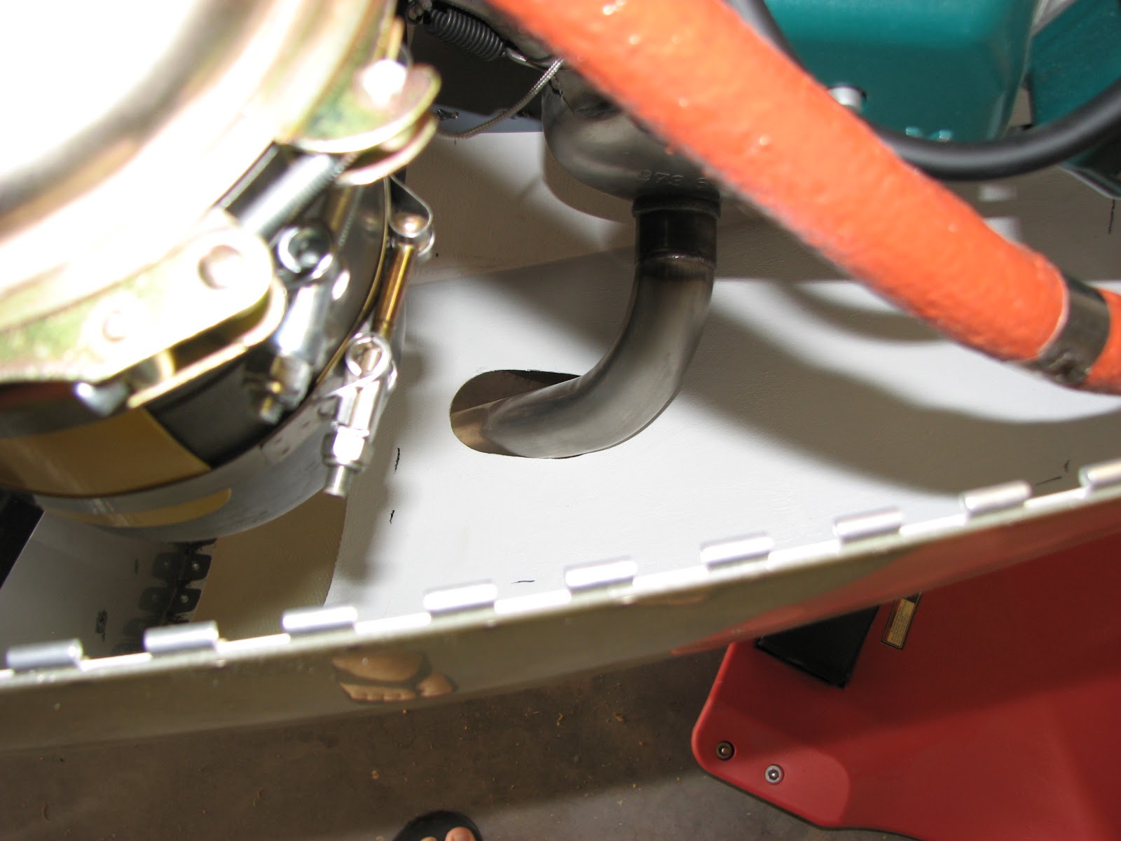
Obviously, the side and the front of the hole where interfering. I decided to loosen the copper nuts holding the exhaust pipes at this point to allow me to wiggle the exhaust a bit to get a better fit.
That allowed me to put the lower cowl fully in place but still the outboard side needed significant trimming.


I drilled some holes along the line and then used the Dremel to remove the material.


I also marked the pipe for later trimming which should make it easier to put the cowl back on.


Now that I had the muffler in its final position, I removed the cowl and re-torqued the copper nuts, trimmed the exhaust hole in the cowl and continued with the application of the heat shield.
The lower part went on ok but I immediately noticed that the left side piece had to get cut off from the lower piece.


Second part was the little right side piece and then the left piece went on. Some of the trimmings were used to fill some bald spots.


Then I applied the epoxy around the edges to seal the foil in. I also used this batch of epoxy to apply the little notice tag on top of the air tunnel.


That was it. Now I have to think about the best way of cutting that pipe. The room is a bit tight for a pipe cutter but that would certainly make the cleanest cut possible. I'll take some measurements and see what I can find.


Sunday, May 19, 2013

Oil Pressure Sensor Mounted

The last step of the Pressure Sensor Relocation was to find a spot on the firewall for attach the Adel clamp and the sensor to.
The hose was not quite long enough to get it all back to the fuel pressure sensor which others used as an attachment point but I found a good route to get it to the GPS antenna shelf.


This position would also allow for a good route without blocking anything important.


and enough clearance at the exhaust if clamped where I put my hand.


Now the only thing missing at the shelf was at least a hole. I decided to install a nutplate as access was easy enough for the squeezer..


That made the installation a one-screw job.


Please note, that I had also installed the clamp at the end of the fire sleeve. On both ends actually.


Crimping on the spade connectors was a routine job but routing the wire for minimum stress and bends was not quite so easy.


Looks like a lot of wire ties but that way the wire is unlikely to break due to vibrations.
This completed the relocation and added another hour to the time balance sheet of this step. Connecting the sensor to the electrical system was the last open step in Section 46 and so I could close that as well.

Next was to catch up with section 49 and install the oil hoses in preparation of the oil cooler installation. But before that, I noticed an interesting schematic in section 46-11 that shows how this fuel distributor block is put together.


This will be interesting in the near future as my engine is one of those that will require the short fuel supply hose from this distributor to the fuel pump to get replaced. This is covered by another SB, but this time issued by Rotax.

With the help of Vielle Burette's pictures posted on his blog, I was able to quickly tackle the question of How-in-the-world-should-I-route-these-oil-hoses question.

I started in reverse order than the instructions ask for as it appeared to be easier that way.


This was the return hose that attaches to the belly of the engine.


By the way, I tried to go below the friction brace too. It appeared that there was less stress on the hose when routed above the brace as shown in the picture.
The next hose was the one attached to the oil pump. Clearance with the fuel spill over pipe was not good and I had to bend the pipe a bit to get the hose to pass it.


I did not do more on this hose and left the support just temporarily attached to the exhaust bolt. This will get completed when I finally hook it up to the oil cooler.
Next was the oil supply hose and that one was the worst to route. I am really grateful that I had a lot of pictures from other blogs to see which way to go. It's really tight behind the engine now.


You can see that I also installed the air filter on this side now. This was because I saw clearance issues with the spill over hose as well as problems to even get the air filter installed at all after the oil hoses were in place. I had to slightly reroute the spill over hose and also routed the oil hoses underneath the fuel supply hose to get a bit more length out of the oil hose.


I had to lift the oil canister up a bit to clear the air filter, so we will see if this is low enough to clear the upper cowl.


This shot was taken from the left side, aiming at the shelf.


Again, from the left side and below so you can see how the hose is resting on the water hoses.


And the final shot that gives you an idea of the clearance between oil cooler and the muffler. This is also the reason why I might have to do this step again. As I had moved my oil cooler about an inch forward of the position Van's had intended, I might now have too short of a hose (on the left side) to connect it to the oil cooler and mount it to the cowl.
It's not a bit deal! If it turns out to be too short I can order a hose, clamps and a longer fire sleeve from Aircraft Spruce and manufacture my own within an hour or less.

Sunday, May 12, 2013

Oil Pressure Sensor Relocated

Initially I wanted to finish the lower cowling by applying the aluminum foil but when I looked into that step a bit more closely I noticed that it would beneficial to have the exhaust and the oil lines pretty much in place. That way you know were the foil is needed most and you don't just apply somewhere.
I was not ready for that but one of the side projects on the way to installing the oil lines was definitely do-able. That was to move the $400 Honeywell oil pressure sensor from the engine back to the firewall where it would be safe from vibrations that obviously kills it very certainly, sometimes within as little as 40 something hours, as some have reported. I did not want to be one of those having to cough up the extra money for a replacement that might just fail before Rotax would reimburse me, maybe, on warranty.
On VAF was an article posted in November 2010 that contained all the relevant details about where to get the relocation kit, what extra parts might be needed, etc.. I can wholeheartedly confirm all that was said in there is true and you should follow that article if you desire to do the same.

The first step is to install the restricted fitting on the 3' oil hose and slide the fire sleeve over it.


I have not put the Oetiker clamp on yet in this photo. The next step was to remove the sensor from the undesired position on the engine. Do not worry. There won't be any oil flowing out there on a new engine.


It came out easily and I was able to clean the engine-side threading with a Q-tip. Some small metal parts and a shaving came out along with the gunk from the Loctite they had used to install it. It is probably the 322 that was also used on the fitting on the belly of the engine as it is tolerant to slightly oily threads.
I also cleaned the threads on the sensor to get that stuff off along with the oil.


Then I had to put on the open fitting on the other end of the hose. That one put up quite a fight I must say. I oil the inside of the hose and the braided end of the fitting but it still did not want to slide into the hose easily.
I worked on this job for about an hour, on and off, and only got it that far:


That was not quite satisfactory - even more so, when I realized that I had forgotten to put the Oetiker clamp over the hose before installing the fitting. The clamp is too small to slight over the fitting, so I had to take it apart again and start again. It did not go easier the second time and I stopped when I reached the point where I was before and installed the clamp.

Then I sealed both ends of the fire sleeve with red RTV.


While the RTV was curing I decided to use the time to clean up another loose end of the engine installation. I had installed a lot of tie wraps forward of the firewall but I did not recognize that none of them were the heat-resitant type, not even the original Van's ones. I decided to remove all of them and install the PEEK ties (brownish) on critical jobs and the less heat-resistant plenum ties (red) on simple stuff. 


The plenum style ties are still much better than the ordinary Nylon type Van's had sent with the kit.
It did not take too long and the job was done, except for one tie that still hold two hoses together where I hope to install the oil pressure sender if the hose is long enough to get there.


The RTV was cured enough to handle it by then and I went ahead and installed the restricted side on the engine, using Loctite 322MS to seal the threads and hold it in place.


Before installing the sensor on the other end I felt it was a good idea to fill the hose with oil to get the air out. The point being that I doubt the oil would escape on the bottom at the restricted end  - or at least so slowly that I could install the sensor with only a minimum amount of air trapped inside the hose. Once the opposite end is closed I doubt the oil would get through the tiny hole on the other side. To hold the hose in an upright position I used the propeller as an assistant.


The aluminum foil on the bottom of the funnel is to tighten the outlet and allow it to get into the hose. It was pretty messy still as I was not able to poor the oil into the funnel slow enough and it backed up with the inevitable spillover.
The last drops were filled into the hole with a syringe and the largest needle I could get (farm supplies). That went much better actually and much cleaner, too. Once the hose appeared to be full, I cleaned the threads from the oil, applied Loctite 322MS to the threads of the sensor and attach the sensor to the hose.


That was it. I removed the tape holding the hose to the propeller and cleaned up the rest of the spillover and put the hose down on the top of the engine. It was getting late and the routing and installing it to the firewall would have to wait.
So far, this job took me 3.5 hours and there is probably another half hour waiting for the cleanup (I have ordered a tool to install the metal clamp on the ends of the sleeve).

Wednesday, May 8, 2013

Happy Anniversary - Again!

As of this day three years ago I pulled my first rivet on the RV-12. As much as I had hoped for there not being a third anniversary last year, I clearly missed the goal.
However, I am indeed in much better shape to hope for finishing before the 4th anniversary would be up. Actually, it looks quite promising at this point that I could finish by the end of this summer.
There are quite some uncertainties up ahead, though. Just things I have never done or seen anybody else doing. One of them is the certification process and the other one is how to move this project to an airport without breaking it.

Monday, May 6, 2013

Section 47 Completed

For now I am done with the propeller and spinner installation. I verified with my angle protractor tool that the blades were within 0.2 - 0.3 degrees. I must have been lucky or incompetent in using the tool correctly. Either way, we will find out when firing up the engine due to the existence or the lack of excessive vibration. So I torqued the propeller bolts to 20 ft-lbs.


I also reinstalled the spark plugs and marked the bolts as torqued.


I even decided to install the spinner at this point and follow the instructions verbatim as I anticipate that I will not change the blade angle before some engine runs and taxi testing and I did not want to lose the gap fillers that do not have a lot of support without the spinner installed.


The spinner aligned very well with the drilled holes and proved that I must have done a good job distributing the errors evenly enough that there was no interference with the fiberglass when screwing the screws in.
Now back to the lower cowl and the installation of the heat reflecting aluminum foil.

Sunday, May 5, 2013

Stiffener Kit Installed

Today the side skin stiffeners were to be installed. I started with marking the rivets on both sides that had to get removed.


In addition to the ones marked in the picture, there are also some on the sides of the firewall that have to get removed but I forgot to take a photo before I drilled them out.
Here is the "after" shot:


This one shows only two of the four rivets to be removed on that FW side. The next two are the ones under that goop (not visible) that right above, on the vertical part of the firewall, the drilled out aft rivet.
After you have removed these, you ought to draw line in the shelf between the two rivet holes.


This line will later be used to match-drill holes through the shelf into the stiffening angle underneath.
But first I had to remove the existing diagonal stiffener angle on the side skins. Van's asks you to cut off a portion that will interfere with the installation of the additional angle inside the fuselage. That's what they had you drill out the upper 3 rivets on the side. However, this approach appeared to be rather hard to turn into anything good. I foresaw the cutting wheel run off and gut into the painted skin and I could not even image how I was supposed to deburr that mess working under the instrument shelf.
So I decided to remove the angle completely, cut off the upper part with the bandsaw and correctly deburr it before riveting it back in place.


The upper 1" or so had to get removed on the side with the little fin.


No way I could have done this working under the shelf!
Reinstalling it did not take any time worth mentioning either.


Back to the instructions. I had to cleco the additional angle in place, check for clearance and proper alignment. Here you see why I had to cut off a part of the diagonal stiffener:


The aft end positioning in the above picture is not perfect. When I drilled the first hole I pushed the angle up a bit before drilling and it turned out just as requested.


I used my iPhone for these inside shots as it is easier to handle than a full-blown bulky camera. After the angle was properly aligned, the rest of the holes were match-drilled from the inside through the skin and clecoed.


This is how it looked on the inside.


But that is not all yet. I had to extend the line of rivet holes on the side skin with a marker to extend all the way to the front end. The hole spacing was 1" so I made my marks, pre-punched and drilled the holes into the angle. This time from the outside. After that the angle gets removed for deburring.


I decided to prime the forward part of the angle that would contact the stainless steel of the firewall shelf. The rest of the possible contact surfaces is painted so I did not bother.


While the primer was drying, I moved on to the right side and removed the diagonal angle.


The fin was quickly removed and the angle deburred and reinstalled. The additional stiffener angle was installed and aligned and the aft most hole match-drilled.


I should have given the iPhone more time focus before taking the shot but you can still see the proper alignment with the existing rivet. All the match drilling followed and this time I did not forget to take a photo after marking the hole line extension and doing the pre-punching.


All went out for deburring and priming again. While the primer on the right angle was drying I started riveting in the left side stiffener.


No surprises while riveting. Some of the rivets are hard to get too though. You do need the close quarter riveter as well as a wedge tool to do a good job. I should have mentioned that you need a 12" #30 drill bit to drill out some of the rivets on the shelf. Those are the same ones that need special care during riveting as you probably guessed.
Once the left side was done I declared the primer for the right side dry enough and installed that one as well.
Again, no surprises.


From the inside the stiffener looks like this:


It is recessed so far that I also did not bother painting it to match the interior. You can hardly notice this thing.
All in all, the stiffener kit took me 7.5 hours to complete. Not a big deal but I also did not have to remove the lower cowl as it was already off. And I am not fully done yet as I need to get some additional Pro-Seal to cover up the newly installed rivet heads.