Wednesday, July 31, 2013

Left Fairing Close to Done

I had to tweak the left fairing a bit more after adding the 3 first nutplates to its circumference. The issue was with the fit bet ween front and back halves in terms of poking out. It appeared that the thickness of the front half varied along the circumference and a closer inspection confirmed that.
I marked the areas and thinned them out on the inside of the front half with the die grinder. This helped a lot but also put some strain on the previously match-drilled holes.
Fortunately, I was able to catch the offset with the #27 drill bit so that there won't be a (newly created) problem.
Finally, I was able to mount the fairing once more to complete the match-drilling and I hope to finish the nutplate installation before the weekend so I can call this one done.


Unforeseen Obstacles

I was trying to finally get in touch with the DAR I had focused on more than a year ago when I last checked the FAA-published list.
You know that if this attempt would have been successful, I would not be posting here under this title. When I started building in 2009, the list of in-state DARs that would be able to do an E-LSA inspection and issue an Airworthiness Certificate (it is function code 47 on the FAA list), was showing enough individuals that it was not a concern. I remember around 3 just in the Tucson area and many more up in Phoenix.
If you look at www.sportpilot.org and the DAR list they had published there, based on data from 2008, you get the impression that there is nothing to worry about. There even were some EAA Volunteer DARs listed that only require you to pay for their expenses if you are an EAA member yourself.
This still was not an issue last year when the FAA list showed at least 3 DARs with function code 47 in whole of Arizona (no-one in Tucson anymore).
This year however, the list is down to exactly one individual and this poor fellow is not just doing experimentals but has a long list of function codes and is probably pretty busy. It might be a red hering but an interesting detail I found is that two DARs on the list whose names I recalled from last year's check, were still DARs but had dropped their function code 47 (at least).
I was not able to get in touch with the one active code 47 DAR yet and so I looked over the fence and checked the neighboring states.

Oops, what a rude wake-up call I got!

New Mexico has none at all, neither does Utah. Colorado shows two and for the whole of California there are 4 on the list. Well, there were 5 actually and the fifth one was even an EAA Volunteer DAR and so I contacted him in the hope he might come out and get the job done for me.

Here's his response:

Hello Torsten,
Thanks for your DAR inquiry.  Sorry to say I am just this moment letting my DAR authority lapse after over 10 years of aviation activity. Sad to say the FAA with their attitude of complete "take it or leave it has forced me to give up the program.  Actually I very much enjoyed doing the work as I am a retired aeronautical engineer, pilot and an intensely active aviation enthusiast. Unfortunately being also an A/P, I/A and being dedicated to following sound airworthiness practice was just not enough.
I do hope you can convince your local FSDO or MIDO to come out and inspect your aircraft. Don't let their weak excuses of work load deterr you. I am also sending this message to the EAA where I have been an active member for some 64 years.
Does anybody else see a problem here?

This was the last EAA Volunteer in the Southwest and there are only 4 code 47 DARs left in California and there are hardly any in the neighboring states. Function ode 46 (Experimental/Amateur Build) is not doing much better either.
And this is a continuous development since I started building, completely disregarding the fact that in 2011 the EAA got the FAA convinced to ease up on the requirements to become a DAR for E/AB and ELSA and put it in the Federal Register. This either did not catch on in the community or the bail-out rate was higher than influx of new DARs.

This is disturbing at best.

I have asked the EAA for help by providing me with a full list of EAA Volunteer DARs in the slim hope that I can find someone who would be willing to travel all the way out to Arizona to take a look at my plane and sign the required paperwork. I will also contact my FSDO and MIDO and try to convince them to perform their duties themselves but I do not know if that will be successful.

At this point I think that finishing the build will take less time than getting the certification process on the road.

Monday, July 29, 2013

More On and Off ...

... for the wheel fairings.
After sanding off the overlapping regions of the glassed bed for the brackets, I had to put the fairings back on, check for proper fit and cleco them together so I could match drill the holes for the inevitable nutplate installation  around the circumference.


But not all the holes were match drilled at this time, no, only three for now. Then the nutplates get installed and then ..... they get installed on the brackets again so the rest of the holes can be match drilled. I assume this is to provide for a better fit.


The nutplates get installed temporarily with the help of a screw to hold them in place while the first hole is drilled. Fortunately, these are for #6 screws which put up much less of resistance when being screwed on.


It was not too long before all three nutplates were installed on both aft fairings and daylight was fading.

To be continued...

Sunday, July 28, 2013

Fairing Bracket Bed Glassed

Tough title, huh? Well, I figured that the whole task of gooping floxed resin around those screw holes was to build a bed for the brackets to rest in and therefore would spread the load of any forces evenly into the fairings instead of a small area around the screw hole.
So, apparently we are glassing a bed for the fairing brackets.
And that's what I did today. First was to apply some mylar tape onto the brackets to allow them to separate from the resin after it cured.


I could not take any photos from the actual flox application as I used 20-minute hardener for my epoxy this time. I was afraid the bead might run down the side wall of the fairing if it would be given too much curing time. As it was hard to adjust the fairing in the right way to get the first screws started, I was running extremely low on time.

The result of the first run looked like this:


The bed was not very supporting, and so I decided to lay it up a second time. This time is it was easier to see were to apply the stuff and it would also stick to the flox that was already there.

While the second batch was curing I started working on the nose wheel fairing. That was 2.5 hours into the work day, so do not expect the glassing task to be a quick one.


The scribe lines on the nose fairing were very thin and it was hard to trace them. Also, the aft fairing had two, vastly different, scribe lines for the wheel cutout. I decided to go with the one that removed less material and it appeared to line up with the front scribe line as well.

After I had removed the excess fiberglass, I deburred the aluminum that will be used in the upcoming tasks.


Then I removed the main wheel fairings from their brackets which was not easy at all as now I had applied too much flox mix and the epoxy had embraced the brackets. After a bit of carefully applied force I got them off. I will have to trim off the excess flox but other than that they look good to me.


I hope I can that trimming work done during the week and finish the nutplates installation on them as well, as to finish the remaining tasks to complete the main wheel fairings.

Saturday, July 27, 2013

Wheel Fairings Fitted

Today was the day when I lost count about how many times I put the wheel fairings on and off the plane. It was final fitting day!

With the left aft fairing on I could get an idea of how much I needed to remove on the bottom to allow for an equal tire clearance.


Also the upper part and the area for the brake line needed some more trimming.


The little markings on the inside of the bottom allowed me to draw a better pattern on the fairing once it was removed from the bracket.


I came up with 3 options for the curve and opted for the middle one. Clearance was looking good after that step.


The brake line had good clearance too but I was worried about the line being too close to the landing gear leg and so I attached a vinyl tube to it for protection, using a heat resistant tie wrap.


On for the fitting of the right aft fairing. That one needed quite some additional trimming.


The brake line was bent downwards at a point higher than the one on the left side. So getting that one cleared from the fiberglass gave me quite some grief. Fortunately this will be covered by the transition fairings.


Then it was time for the front fairings, starting on the right. I connected the two halves to see how they fit together and if they aligned with the mounting holes.


It actually made a difference how the gap fit around the gear leg if the halves were connected or not. Connected they looked perfect.


Trimming the clearance for the tire on the front fairing was easy. Do not bother to mark this while clamped to the bracket. Just take both halves off and connect them together while on the work bench. Mark the extension from the aft fitting on to the front fairing. Done.


The clearance on my aft fairing was around a finger thickness. So feel your way around the front clearance when clamped back on to see if it needs more trimming. On to the left one.


That went just as well and looked really good once back on the brackets.


Next was to kind of match-drill the #30 holes that were currently clecoed "into" the nutplate without actually touching the nutplate. This is somewhat delicate to do as the drill bit pulls forward once it catches on the fiberglass. I had to go slow and use my second hand to provide resistance to the drill to hold it back.


I used Boelube as usual on the new nutplates when putting those screws in. It is much easier than running them in dry.


Same procedure on the right side.


I would have liked to set the bed of epoxy and flox so it could cure overnight but after 4 hours in the humid heat I felt that I had enough. I figured that I could let the epoxy cure while working on the nose wheel fairing which I have not yet started.

Thursday, July 25, 2013

First Trial Fit

When getting back from work, I briefly slit the left aft fairing onto the wheel.


Clearly the brake line is the problem for the fit. Other than that the adjustments needed appear to be minor.

Tuesday, July 23, 2013

Another Long Day

I had taken another day off from work to continue working on the wheel fairings. In the morning I taped the two halves of the fairings together and match drilled the dimples into the flange.


The same happened to other one.


Then some measuring was in order to mark the cutout for the gear legs.


Before doing the actual cutout, I decided to jump ahead and deburr and prime the brackets, so they would be dry when I was done with the cutting and trimming.


Then back to the fiberglass and cutting out the gear leg cutout with the Dremel.


I trimmed out the rough cut with the sanding drums of the Dremel.


The right one followed with the same procedure.


The primer on the brackets had dried enough to handle them and so I riveted the nutplates on.


The next step was to attach these brackets to the axle and to the gear leg. I had already mounted the necessary hardware before installing the wheels, so I did not have to take the wheels off at this point.


And the same on the right side.


Lots of Loctite was applied when installing the bolts.

Next step will be to try the pants on and I expect a lot of trimming before they really fit.

Monday, July 22, 2013

Wheel Pants Fitted

I took a day off from work today to work a bit more on the plane and I put 5 hours into it. Yet, I don't seem to have a lot to show for it. The instructions in section 36 are rather misleading and therefore I spent way to much time of sanding edges to match that were not anywhere near the required line. However, that was not obvious until working on the following steps.
So, to save you some time, in case you are following me doing this, do not worry about sanding accurately to the scribe line on the main wheels front fairings. Go all the way to the line as quickly as you can and then connect the front and aft parts and see if the dimples for the screw holes attaching the fairings to the bracket are lining up with holes in the bracket. Mine were way off, to the point that I could get only one side inside the holes while the other pair was far outside of them.
Once you find that you get closer to a good fit of those dimples, then it is time for some accuracy in matching the edge of the front fairing to the recess in the aft fairing.
That way you should be able to rather quickly get this task done that took me 5 hours overall.


One done and one to go. By the way, I have searched other blogs for pictures of the wheel cutout in the making but no-one was daunting enough to show those. Mine has a surprising lack of line-up although I have accurately trimmed front and aft fairings to their respective scribe lines.


Once they are connected I can trim this offset back and hopefully smoothen this out a bit. Not that anyone would ever see it unless I'd be flying way too low....

And finally the second set of fairings was trimmed too.


To be continued ...

Saturday, July 20, 2013

ADSB-in Works!

In the morning I got the Avionics system ready for another test and I hooked up an antenna to the ADSB-in box temporarily. Finally, a good experience with Dynon. Nothing to complain, everything worked just by flipping a switch.


The ADSB-in is hooked up to serial port #2 and once I selected that it attached to a ADSB-470 it immediately worked. The ADSB-470 entry is pretty far down the list which appeared to be sorted by Dynon products first but then the ADSB box showed up way down along with other non-Dynon stuff.


You will see an additional active ADSB status page that shows you when you received what kind of information and how much of these packages you received since power on.
Great stuff, I could see a thunderstorm developing around me on the map display before I heard the first thunder. Unfortunately, I did not take a photo of that.

I disconnected the antenna and prepared for the installation of it. For routing the wiring I got some nice self-sticking foam clips. I think they worked great. The adhesive is made by 3M so it should stay on for good.


So I drilled the previously marked holes into the belly and deburred them.


The inside had to get treated with a Scotchbrite wheel to remove the primer and allow for electrical contact. I removed the primer generously around the stud holes and applied Burndy Penetrox A which is a di-electrical grease for protecting aluminum to aluminum or copper joints from oxidizing. It is a proven product with RF connections in Amateur Radio, so I thought this should be doing the job for my application.


Now, between the backplate and the primed inside of the fuselage I decided to place a star washer to promote electrical connection to the fuselage. I used the ones that are round and smooth on the outside and have their stars on the inside.
The studs would then get one star washer (regular, stars on the outside), a washer and an AN365 lock nut once they poke through the belly. For weather sealant I used the EAA recommended DAB sealant.


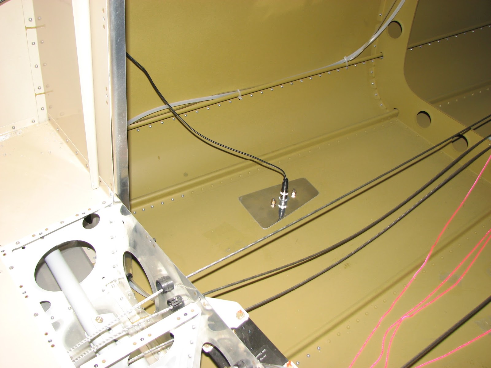
I needed a second hand to hold the sealant smothered antenna in place while I was trying to put all the hardware on the studs from the inside. My wife "volunteered" and did a great job.


A 2' cable is enough to connect the box to the antenna and I quickly verified that everything was still working great. By the way, the antenna position I chose is 1' aft of the bulkhead rivet line and 10" outboard from the center rivet line on the tailcone.
All the antenna cables in the lengths I needed with sometimes odd combinations of connectors I got at Cables On Demand. I really liked their quality and the prices are great, so I thought I mention that here, in case you are trying to find a source.


Then I went on to install the transponder antenna for the Passive Collision Avoidance System (PCAS) that I plan to install after certification. Putting the antenna in at this point is way easier though. I used the exact same position as with the ADSB antenna, only on the right side this time.

But first I ran the cable path, also on the right side. I could not use the smaller snap bushing as the SMA connector on the cable would just not fit, so I had to use a slightly larger size.


I found a nice spot next to the map box and allowing the antenna cable to be routed next to the POH tray. You can see the rivet holes for the outboard flange of the tray aft of the snap bushing.

The only other bushing was required on the aft bulkhead.


The cable will sit way below the top edge of the fuel tank and will not be visible once the tank is in.
The forward route was a copy of the ADSB wires, under the canopy deck.


Installation went just as well as the ADSB antenna, although I have not yet tested if the installation really works.


Here are both antennas in perfect harmony (hopefully not from an RF point of view!).


This reminds of the beautiful cars they built in the 50's.....


I did not have enough of those foam clips for the wire on the right side, so I will have to clean that up some time next week when I get more supplies.