Wednesday, December 29, 2010

A Little Bit of Everything

I continued with Section 20 this morning but there was not much more to do before I realized that the next step would be priming. And as I decided to use a fuel proof epoxy primer for the fuselage interior (for the obvious reason that the fuel tank is inside) which wouldn't arrive before Thursday, I had to hold off on that. All I could do was countersinking the angle and dimple the corresponding holes in the aft bulkhead.


To not lose the whole day I started on Section 21 and prepared some parts that will be riveted to the center section soon and therefore also need priming, the floor boards and the aft ribs as well as some small parts. I deburred them and also did some dimpling one the floor boards and the ribs that share the nutplate line.


The Stewart Systems primer is supposed to arrive tomorrow, so I see that I get the parts prepped for priming before the UPS guy comes along. That'll be tough as we are having a cold front moving through and it'll be stormy, rainy and around freezing, so playing with water and working outside is not real fun anymore...

Unfortunately, the replacement skin for the flaperon won't make it here before Monday, so it'll take a while before I can revisit this screw-up and try to determine what went wrong.

Tuesday, December 28, 2010

Fuselage Started

Today I started on the fuselage after finishing the right flaperon by putting the rod end bearings in and fixating them with Loctite. When the Loctite is cured I am going to cover the bearings up with blue tape to keep dirt out and masking them for painting. I had overlooked the note from Marty Santic to leave the bearings out until final assembly until it was too late as I had the Loctite already put on. Oh well, I guess it'll have to do now.
The Loctite is supposed to cure for 24h so I left the flaperon on the main work bench and as the secondary work bench is covered with tools, I need a place where I could start building the fuselage. The folding tables are really universal!


Then, right on the first step of working on the wing receptacle of the fuselage something happened that hasn't happened during the hole build before and that I had read so much about in Dave's blog! A pop rivet's mandrel broke off in the riveter. It's this kind of rivet Dave had complained about so often, the CC264 a small AD3 size pop rivet that I had no problems with before. I used a full size hand riveter when it just broke off.


And then it happened again, right on the same nutplate with the same riveter. Incredible! I then used the close quarter riveter for the next nutplate and everything worked ok. I wonder if it's a riveter or a rivet problem. The ones I had before where black in color with a silvery mandrel. The set I got with the fuselage kit are all gold.


The rivets sit tight and using a hammer you can punch the mandrel out the other way. That's ok with this type of rivet as the mandrel isn't supposed to break anyway but gets completely pulled through the hollow rivet.

After this little intermezzo I went on to the real job in this section. Matchdrilling! Therefore you have to place the wing receptacle with the rear bulkhead clamped to it onto the bottom skin and cleco the bottom flanges to the skin. This sounds easy but it isn't. The problem is the size, weight and flimsiness of the parts involved.
Basically you have to get access to the bottom of the skin to cleco the flanges while the heavy center section is attached to the skin. All without bending and possibly damaging that large but thin bottom skin. I saw in Dave's blog that he flipped the parts upside down which is hard to do alone and you need a lot of support piece that I just didn't have to keep the parts straight which I just didn't have. So I came up with something else that I could do alone. I built up some support on the bottom where the skin rest on securely while giving me access to the center section to cleco the flange to it.


Well, this look ok to work on but you didn't see the trick yet. A shot from the side that shows the tunnel that I built to get access to those vital holes. Just enough room for a hand with a pair of cleco pliers holding a cleco. Clecos already put in for clarity :-)


The rear bulkhead is a bit shorter, so the whole section was leaning towards me when I was trying to drill a straight hole in this piece. To make it easier for me to see the reflection in the aluminum I supported the rear bulkhead side (which is the front in the picture) a bit more before starting drilling.


Ready to go! God, I always loved my little Sioux drill but today I found out how much I really love it! This little devil was eating through that thick aluminum angle that was supposed to get match drilled like it was butter. I put a new drill bit in after I had possibly dulled it a bit drilling the counterbalance tubes, but still - the drill did a great job - while being not too loud at all.
I think it took about 6 seconds per hole. I added a drop of Boelube for every hole to make sure the cut off would easily move out of the hole during drilling. About half time after around 45 minutes as I was very careful making sure the hole was perpendicular to the surface.


And another 45 minutes later it was done. What a mess on the floor though!


Cleaned up the mess and took two more photos to verify that I did a pretty good job staying straight while drilling. Yeah, I need that pad on the shoulder after the left flaperon experience.


I took the parts apart and deburred the match-drilled holes before calling it day in the shop. That was a nice start in a new section!

Monday, December 27, 2010

Right Flaperon Done

It seems I'm slowly getting over my bad I had with the left flaperon. After Christmas I went back to the shop with a lot of energy and the intent to get going on the right flaperon as the left one is waiting for the replacement skin to get here.
I had the internal parts all drilled and deburred last time, so it was right to the riveting. Knowing what was coming I was better prepared this time for dealing with the actuator bracket and so it didn't take a lot of time to deal with that. The hinge brackets went on quickly too and there I was putting the skins on already.
This time I was very careful not crease the wing and I put a layer of cardboard (the corrugated type) between the wooden board I used for pressing down the skin and the aluminum. This worked just fine.
I didn't take photos until I was over the stage of riveting one side of the skins on and I had to turn it over to prepare the other side. Call me superstitious, but it worked.


The second side was riveted successfully, too and it was then on to put the outboard nose skin on. This one is the only tricky one as it has to smoothly flow around the counterbalance weight tube as well. I riveted every other rivet in the bottom line along the spar first, then turned it over to do every other rivet on the top spar line and then the leading edge line before doing the rest. I believe it distributed the tension a bit and made it follow the line a bit smoother.


The fit was much better than with the left flaperon and so the riveting went pretty quickly. Remember, I had drilled the leading edge holes with a hand drill!


The other nose skins came on after this, after a lot of deburring to make sure the overlapping skins wouldn't cut each others. A lot of riveting again, it's amazing how many rivets are just in the flaperons... On the middle and outboard skin I riveted the bottom spar line first.


Then I turned the flaperon over and tried to pull the skin back with one hand and put a cleco in with the other. No chance! The skin was really resisting to get into its required shape. In lieu of a helper I used a piece of blue tape to hold the skin down after pushing it down with both hands so I could get a cleco started. After the first one is in, the rest follows easily. Soon the top was riveted too.


The last step is to put the clevises in but I haven't had enough energy to do this tonight and left it for tomorrow. After all it requires some precise measurement and medium strength Loctite to hold it in place. A real good chance to mess something up.

By the way, I took a look at the profile of the flaperon. This right looks much more like I had imagined it. I'm still not sure what all went wrong on the left side to cause so much more trouble ... I think I have to be very careful to fix all these things when I revisit the left flaperon.

Friday, December 24, 2010

Flaperon... continued

This morning I took a look at the left flaperon and I saw that I had creased the main skin in a few spots which had escaped me yesterday. Fortunately it was the outboard skin only and I checked in the Van's store that this skin is just $25. That made it pretty easy to decide that I drill out 132 rivets to get the skin out. I ordered the replacement skin right away and also another 300 LP4-3 rivets - just in case.
In the afternoon I drilled out those rivets and removed the skin, cleaned up the mess the drilling left behind and put the flaperon away as I don't want to continue without the outboard skin in place. The whole structure is very flimsy with just one skin on.
I also revisited the actuator bracket and polished the spots I had nicked yesterday when squeezing the solid rivets.

Then I dared to open yet another chapter in the flaperon story. I started the right flaperon! With the knowledge from screwing up the left one, it worked a bit better this time. I finished all the match drilling on the stainless steel tube and I did a completely different approach this time. After clecoing the skin on and adjusting everything for a nice fit - there still was some weirdness about how the skin was bulging along the main spar and it needed a lot of clecos to stay flat in place - I started to dimple the tube again by pre-drilling with #40 bit. I dimpled a bit deeper than before and I had the feeling I could keep the drill in place and push through, so I did. One hole worked fine and so I went on to the next one and that one worked fine, too. So I ended up pre-drilling all the holes on the nose skin side by hand. I had already drilled the outer two holes that connect the tube to the nose ribs on the drill press as I did with the left one. I was wondering about doing the final drilling on the clecoed structure as well and gave it a try with one hole which worked out fine again. I ended up also final drilling all the holes manually. I think I did a good job, we'll know for sure when I rivet the skin on. If you follow this technique, make sure you apply Boelube to the drill bit with every hole you drill. Especially the #30 got pretty hot occasionally and I saw the Boelube evaporating right before the drill broke through the steel.
I took the structure apart and deburred everything and that ended the day in the shop today.

Sorry, no pictures but there wasn't a lot to photograph anyway.

Thursday, December 23, 2010

Flaperon Nightmare, Part 2

Today I have decided that I am not impressed with the engineering and the manufacturing of the flaperon parts of the kit - AT ALL. There is just too much weird stuff going on and some things just don't fit right. The previous story about the stupid way how the actuator bracket gets riveted to the spar is just one example. Later in the afternoon when I got over my frustration and back to the shop the story continued and didn't get better.

So I continued to add interior parts to the spar. Pivot hinges, nose ribs, main ribs and the dreaded stainless tube (oh, another example of what's weird about the flaperons - what were they thinking telling you to use a pilot hole in thin soft aluminum to drill into a hard and thick piece of stainless steel?).


The main skins got clecoed on after thorough deburring (their edge will be underneath the nose skins, so the outside should be smooth).


Then they got riveted onto the ribs (not on the spar as the nose skins have to overlap before we can do this) and the inboard nose skin gets clecoed and riveted on. So far so good!


While riveting the skin onto the outboard nose rib it happened! An ugly dent caused by the rivet!!! What happened?!


A closer look reveals that all three rivets on the nose rib pushed the skin downward where there was obviously not enough support as the nose rib appears to be too low in profile to match the shape of the skin. What the &*^%!#@ ??? How could that happen? All nose ribs are alike and it seems to be ok on the inboard side (which didn't get riveted yet indeed). Well, it's too late now to support the skin with a washer of some kind to prevent this from happening but this sure looks like crap!
Did I grow to accustomed to the Van's precision manufacturing that I didn't even check the fit before riveting? I guess so!

And this is not the only misfit!

Look at the light around the rivet lines on this shot of the nose skin overlapping the main skin on the bottom of the flaperon:


You can see that the nose skin is obviously not completely flat where the rivet line is. A look from the side shows the profile of the flaperon on the outboard section looks it's a bit hollow behind the leading edge. I wonder if this is how it should look like?


Whew, I'm really devastated how this left flaperon is coming out. The outboard edge is not even the worst as these dimples can get filled and sanded smooth but I am surprised that for the first time I can't rely on the superior kit quality of Van's and have to check every little detail before riveting. If there's more going wrong with the right one or with the rest of the left one I feel like I want to trash them and order a full set of flaperon replacement parts and start from scratch!

At least the rest of the surfaces look good in the reflections.


I hope this all looks a bit better in the morning!

Merry Christmas, guys!

Flaperon Nightmare

I don't know what it is about these flaperons but no other part of the plane has given me so much grief so far like these little control surfaces. I wanted to go into a nice riveting session at right at step 1 it all came to a screeching halt. Why? Lokk at this:


My nicely manufactured actuator bracket wouldn't allow me to rivet it onto the spar because the inner row of holes is so close to the web of the bracket that the heads interfere with the web. The rear one in this image only sits deeper because I had filed away some of the material colliding with the web.
Now what am I supposed to do? I've seen this problem in other blogs but not as severe as I see it with my bracket and removing half of the head can't be the way to put these rivets in. Sure enough Van's is closed now and my only hope is the forum. I'll post this question in a minute but I don't have high hopes.
I wonder why Van's placed these holes so ridiculously close to the web. There is really no need to do this...

The forum was helpful, as always, but that alone didn't solve the problem as you also have to have the right tools to get this job done. The squeezer dies I had received as part of my tool kit wouldn't have done this one here. Fortunately, I had acquired a shortened cupped die to squeeze the long rivets in the pneumatic squeezer.
But I am getting ahead of myself! The solution to this riddle is to put the manufactured on the back of the bracket, touching the spar. I had this idea before but then dropped it right away as my flat counter dies all had a diameter that would have not allowed them to pass the web of the bracket. The forum insisted on either driving the rivets in from the bracket side with a hammer or other means of a lot of force or going at them from spar side.
I tried to use the squeezer to press the rivets in, using a nut on the opposite side as an anvil (while not squeezing the rivet flat) but the rivet head had such a severe interference with the web that even the squeezer could not completely get it down. I didn't want to force it beyond this, so I thought about the backdoor approach again. I needed a counter die small enough in diameter that it would clear the web...
The only thing I had was this combo:


Both dies are cupped. On the base is the shortened cupped die and on the top is the standard length cupped die. Side effect was that the shop head of the rivet has rounded sides. Looks nice and should still work as if it was a standard flat shop head. This way I could just get enough clearance (the standard length die formed the shop head) to get passed the web. And it still marred it!


ok, that solved the immediate problem. I still can't believe Van's would do such nasty engineering on a vital part of the plane though. If the actuator bracket fails you lose your aileron control. What a nightmare! Why didn't they use a T angle instead allowing for two rows of squeezed rivets and a little bit more clearance to the web so you could actually squeeze them without so much pain?!
I have no clue! Anyway, after this excitement I took a little break.

Tuesday, December 21, 2010

Another Long Day with the Flaperon

These flaperons sure are a piece of work! Today was the day to match drill the counterbalance tube and I had dreaded this job. Apparently the steel drills much slower than aluminum, giving the drill bit ample time to drift off and elongate the softer aluminum used as a guide to start the hole. The forum was very helpful how to deal with this issue and I decided to go with the mark or dimple (by just starting to drill a hole with a #40 bit) the steel and then drill the hole using the drill press with a tube support to hold the tube in place. I tried to be very careful again and took a lot of extra steps to make sure the holes would end up in the right place but I did not succeed with three of them. The bad thing about it is that I actually don't know what happened and how I screwed it up. Which is particularly bad as I will have to do another flaperon and have yet another set of chances to do the same (unknown) mistake(s) again.
I don't think the screw up is so bad that I would have to get replacement parts and it appears to be fixable but still my ego is hurt. With all the extra effort I took to make sure it was done right I didn't really expect anything like this. Mainly slightly displaced holes that in order to match drill them caused a slightly elongated hole. The rivet seem to have good grip though and it's in a non stress area, just holding the skin down, so I guess I'm good.

So, this is what I did. Placing the tube on the outboard nose ribs and marking the holes to drill with a Sharpie.


Then taking it apart, pre-punching the marked holes and putting the steel tube in the drill press. Use lots of Boelube, slowest RPM on the drill and don't press too hard. I actually relieved the pressure on the drill every other moment and pushed it back down thereafter to allow the oil to get down in the hole. I drilled the first hole with a #40 and then opened it up with a #30.


Put the tube back on the ribs, put a rivet in to see if it fits nicely - it did.


Now it was to put the skin on. I didn't rivet the two ribs to the tube yet as I wanted to mark the holes in the nose skin and then drill the holes on the drill press again and the ribs would have been in the way for that.


You really want to make sure you flute these two ribs thoroughly or you will see the edge protruding under the skin like this!


So back to the drill press it was. Unclecoed everything and also re-fluted that outer rib that would show. Fluting alone wasn't enough, I had to add some stronger deforming powers in form of my thumbs and unbeatable will.
Here I am drilling the holes I had dimpled with a #40 bit when the skin was clecoed on. I am drilling with a #40 again and I intended to do the match drilling to #30 with the hand drill when the skin is back on in case there were slight misalignments.
I also didn't just start drilling into the tube. Just as I had done it before with the two holes matching the ribs, I started the drill with some pressure and my hand turning the spindle to make sure the drill would stay in the dimple and start without wandering off.


Well, and then back to clecoing in the skin over the tube. That's when I noticed that the further I went towards the inboard end the harder it was to get those clecos in. It looks like a warping issue as it felt like it was progressing. The three inboard holes have elongations with the most inboard one having the worst. Before I was dimpling the holes I made sure the spar was sitting on a flat surface and that no forces could bend the spar. I have no clue at this time what caused this. Bummer!
Anyway, I match drilled as I had intended to and that kind of fixed the problem with the aforementioned elongations.
I took all the parts apart and deburred the holes and edges and threw some rattle can primer onto the surfaces that will have contact.


Although my mood was abit down after this episode, I kept on pressing and riveted the inboard actuation ribs.


I also match drilled the actuator bracket and the two hinge brackets for the left flaperon, deburred and cleaned them and threw some primer and let it sit over night to dry before riveting them on tomorrow, if I find the time.

Monday, December 20, 2010

Flaperons Started

Today I started working on the flaperons for real. The previous little cutting session doesn't really count for that. Not after spending 6 hours on manufacturing these little tie down hinges and the two actuator brackets. I was very careful and diligent to avoid a frustrated order for replacement parts from Van's and I might have succeeded. I'll find out when I actually try to mount the flaperons to the wings.

You know I had already cut the extruded aluminum into separate pieces. One guy on the forum actually recommended against it but in this rare case I don't agree with him. I think it is really no big deal to drill straight down the 4 tie downs to widen the hole before tapping them. It would be much more tricky to find a straight drill to drill the whole 9" tie down in one step and I doubt you could find a tap of that length either. Anyway, I explain how I did it with 4 2" tie down pieces and you can decide which way you wanna go for yourself.

It started with drilling a hole into the two pieces of angle that should become the actuator brackets. The hole has to be as close as possible to the upward flange in order to accomplish the desired stress relief. I did that on the drill press (allow for the drill to move a bit with your favorite cheapo press from HF. As you can't pre-drill this hole, you should know how much drift you have to compensate for. To find out, use the left over scrap angle.) I didn't do this and learned this by offsetting the first hole by 1/32" which I considered to be good enough to keep the part.


I did every step of the process on both angles before moving on. The same is true for the 4 hinges later in the process.
Then I used the bandsaw the make the first cut removing the flange. Try to cut as close to the flange as possible as any leftover will have to get filed and polished down to match the rest of the surface. An AN3 bolt with washer will go into the hole that is about to get drill into the flange.


As mentioned, the hole for the bolt has get drilled. I used a scalpel to cut a little cross into the aluminum where the hole should be. I was able to feel that cross section when following one line with the tip of a center punch. That way I had a pretty precise starting point. I pre-drilled that hole with the smallest bit I had, followed by a #30 drill bit. Then opening it up to the 3/16" requested in the plans. Only to find out when trying to put a bolt in that the hole is too small for an AN3 bolt. I opened it up with #12 bit and that worked perfectly.


I used a file to reduce the "burr" where I had cut the flange off before. When I got so close to the flange that I couldn't make sure to stay away from the flange I stopped and switched to the 6" Scotchbrite wheels. I have the Cut & Polish wheel as wheel as the grey one for fine polishing. The coarser Cut & Polish helped me a lot to remove the burr fast.
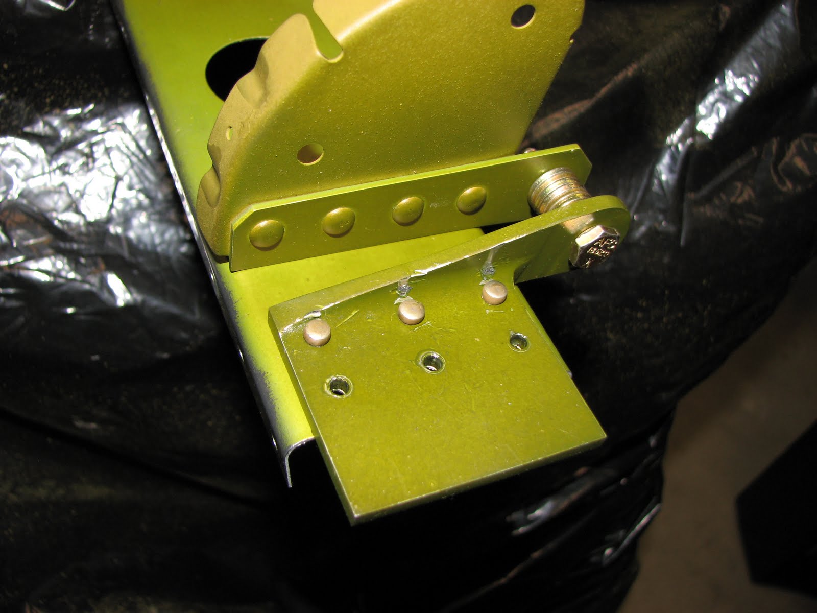
The only problem I had with that was that I somehow canted the angle a bit which left a not perfectly smooth surface on one angle. The other one is perfect. Nothing problematic for the bolt though. The light in this shot amplifies the corrugation.


Another hint if you do this with the SB wheels. I removed the side covers from my grinder to allow me to press the angle on the flat side of the polishing wheels. That way I didn't have to worry about accomplishing a flat surface.

Then it was on to marking for what looked like a more complicated shaping cut. My first problem was how to (at least roughly) mark a 3/8" radius around the bolt hole. On my search for something that could help as a template I found out that the diameter of a penny is exactly 3/4". Bingo! 3/4 dived by 2 is 3/8. Just the radius I needed. If you look closely you'll see that the gap between the center pillars of the Lincoln Memorial where it meets the base is either the center of the penny or so close that you can assume it to be correct. I marked it with a Sharpie and was able to the center the penny over the drilled hole by centering the Sharpie mark inside the hole. The rest was easy and so the brackets where ready to get cut.


The bandsaw did the job quickly, leaving some ugly rough cut parts that were in desperate need of some adjustment with files and the Scotchbrite wheels.


After applying some TLC to these rough cuts the brackets quickly turned into some presentable parts.


Then it was on to the tie down hinges. The main problem here was to make sure that your drilling and the tapping are done straight. The fact that there is already a hole in the tie downs makes this much easier. I clamped one tie down piece in the drill press vise and used a drill bit that is just big enough to slide into the existing hole to center the assembly. In my case it was 9/16" drill bit that did the job.
Once the setup is aligned, I remove the 9/16" drill bit and put the one in to open the hole for tapping. It should be a Q drill bit but I didn't have one. The manuals suggest a Q or a 11/16" but I feel the latter would be too big. I had a 21/32" drill bit and this is what I used.
So I put the 21/32" bit in, added some Boelube and drilled along. No problem at all. The holes all came out very straight, very smooth.
Now the next step is to align the pieces for tapping. This time you use the drill you just used for opening those holes for straightening the setup, in my case this was a 21/64" bit.


With the piece aligned, you then replace the drill bit with the tap. Make sure you put it in deep enough so the brackets of the drill spindle are touching the tap on its main round part and not on the square section as it would put the tap off center. You can turn the drill on to make sure your tap is aligned.
Then you use one hand to push the drill down onto the hole while you are turning the tap with your other hand and start the tap. When it gets a bit tough to turn the tap by hand, back out by turning the tap the other way while you're still supporting the tap with the lever pulling slightly down.


This left a thread of about a 1/4" in the hole. More than enough to continue tapping manually now but this way you made sure you are perfectly aligned.


After this major task, it was time for the details. In this case you're supposed to drill a #30 hole into flange, probably to cleco it to the spar and then match drilling all the other holes. I used a scalpel again to cut a cross into the aluminum and I marked the part on the back as it was easier to measure the required distance from the center line. Placing it on a piece of wood and drilling it with a small drill on the drill press made sure the bit wouldn't wander off.


Then I turned the hinges around and drilled them with a #30 from the other side as it was easier not requiring the wooden support.


The final chapter was optional as it is a weight reduction cut on the hinges, removing a triangular shaped part that is not required to support the hinge bolt. I decided to use my hacksaw on this delicate cut as I was a bit afraid to lose a limb fiddling with a tiny aluminum part so close to a fast moving saw blade on the bandsaw.


This attempt was not very successful though. Not because it couldn't be done but because almost all the teeth on my hacksaw's saw blade were gone. In lack of a replacement blade I faced the danger and used the bandsaw instead - very carefully!
In a few minutes it did all the required cuts and none undesired ones(!) and after some additional treatment from the dynamic Scotchbrite duo, the hinges were done.