Sunday, February 27, 2011

Main Fuel Lines Installed

I extended the existing main fuel line (as opposed to the return line) from the fuel forward to the fuel valve. This is the first tricky fuel line as you start on the work bench but then when a few bends have been added, you have to install the straight line through the snap bushing and finish the flare on the plane as you wouldn't be able to get the flared line through the bushing.


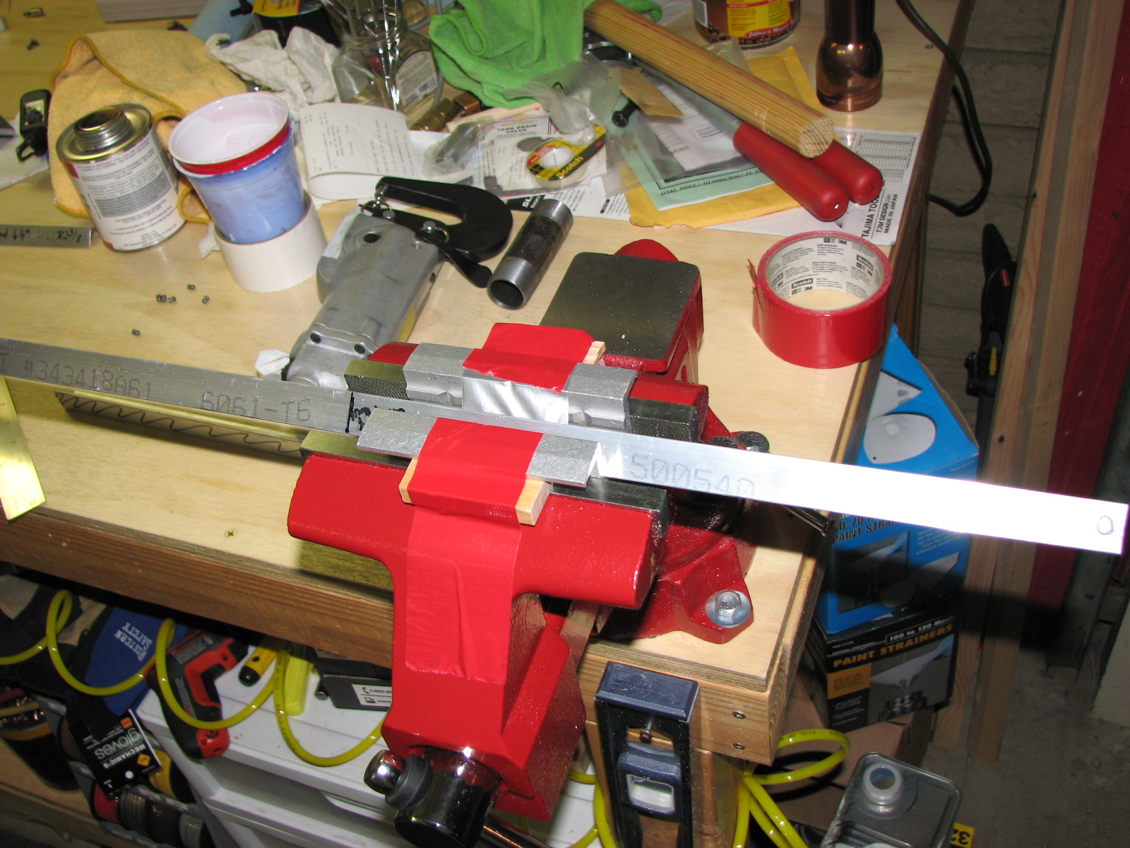
This line is actually really long. It runs through the tunnel between the bulkhead that supports the wings passed the mixer and though the forward bulkhead that supports the seats. That's the area where you have enough room to put the final flare on. Don't worry about bending the tubing upwards as the radius is very wide and will easily get removed afterwards.


The ability to pull the line back a bit and bend it upwards to have a little room to finish the flare (do not forget to put nut and sleeve on before you do or the line has to be cut and removed!) is the reason why this last bulkhead hole right before the valve has been widened and has no snap bushing to guide the line.


The fact that you can shut off a valve was very helpful when I did my blow test after tightening down those nuts on the flares.
The next steps were preparation for more tube bending. I needed to install the connection points for these tubes. So, the gascolator and the transducer (fuel flow detector) got their fittings and plugs installed. A word of caution about the hole in the firewall that should allow for the fitting to screw into the mounted gascolator. I had widened this hole and remove the flange that covered that hole early on before riveting the lower firewall to the fuselage. I used an actual fitting to check that there was enough room. My assumption was that there was nothing for me to do or even check when I screwed the gascolator in place. This was wrong. And this was worsened by the fact that it needs quite some time to screw those AN3 bolts in and out on the gascolator as they are not easy to get at. You need a simple wrench and you can't move it more than a quarter of a turn before resetting it. So, when you do this, just screw in the bolts hand tight to get an alignment. push the gascolator to the firewall and verify that you can screw the fitting into it from inside the firewall. I used a Dremel to widen the hole a bit on the lower side. It turned out that the gascolator sat a little too low and therefore was off center with the fitting hole in the firewall That's was caused the problem.


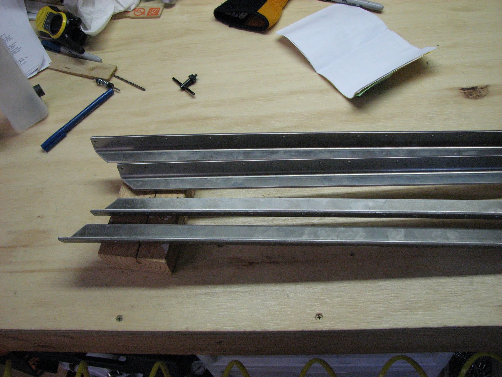
While the thread sealant on those fittings got some time to set, I continued working on the tubings that would eventually connect them. First the short transducer/gascolator tube got bend and flared.


This one was easy as it could get finished on the work bench, so on to the longer one that runs from the valve to the transducer. This one I had to bend completely but leave the final flare off as it would have to get pushed through a snap bushing again.


Notice the little S bend on the left side that doesn't have the nut installed yet? This is particular for the FT-60 transducer that I have. Apparently there are two different transducers used in RV-12s and the FT-60 needs an additional offset bend to get the tube a bit higher to where the fittings sit. This adjustment was holding a surprise for me at this point.
So I pushed the unflared end through the bushing, attach the flared end to the valve to get the adjustment and length right and then I noticed the surprise...


The line looks absolutely perfect. Follow it from the valve through the bushing up to the transducer. Can you see the surprise there?


Yeah, right! This offset didn't get me to the fitting, did it? Sure the tube is too long but that's part of the exercise here as I was to mark the correct length in this step too. Now, as the tube is not where it was supposed to be I first had to take care of that. The distance to the fitting is almost two pipe diameters. Out with the tube, creative free hand bending (with the help of the bending tool), some cursing, in though the bushing, some more manual fine adjustments, marking the correct length, and out again, cutting and deburring of the cut end and back in again, some more cursing about the confined space to operate the flaring tool, double checking that the nut and sleeve are on and flared. Whew! After this fast forward I saw this:


A much better fit although the line looks a little abused. Not a biggy though as it will be covered by the tunnel covers. Only you and I know about it ... ;-)


Compared to this back-and-forth action the final installation of the line between the transducer and the gascolator was a piece of cake. I took care to cut the tubing as long as Van's requested in the instruction. However, the gascolator line appeared to be a bit short. It turns out that this could easily corrected by pulling the S bend apart a bit to allow for a perfect seat on the fittings.


I blow-pressure tested the line up to the valve. After that I needed a second person to seal the open end and there's was no one else around. So, I have to do this when I wife gets back from San Diego tomorrow.
The fuel supply lines are done. The next step is to provide the fuel return line.

Saturday, February 26, 2011

Section 28 Started

Today was the day I started on the fuel line installation. With my previous experience from bending the longerons I was extremely cautious this time to make sure I understood what I had to learn about the techniques involved before doing any serious work. I had never done any plumbing work of any kind beyond using a garden hose and so I had to learn quite a bit. But first I noticed that the Avery tool kit did no come with a little tube cutter and so this mandated a short trip to Harbor Freight to get an adequately sized cutter. Turns out they have a great little inexpensive tool which is perfect for the job. HF #40913 is sold for $5.


Once I had the cutter I started on section 28 and noted that I first had to do some basic installation type of work before getting to bend some tubing. I had to assemble the fuel valve and install some fittings on the fuel pump before installing it on the mounting bracket.
Getting the knob installed on the fuel valve lever was a bit confusing as the instructions asked you to first drill a hole with a #16 bit and then to open it with a #11. Looking a little closer at the drawings and rereading the text, I noticed that you're supposed to drill through the knob with a #16 bit to make room for a screw that will hold the knob on the lever. After that you pull the lever out of the knob and drill its hole open with a #11 to clear the screw. Aha! Funny though that when I tried to open that hole I found that the lever had already been drilled to a #11 by Van's. Duh!


For these fittings I needed the thread sealant Rectorseal No. 7 I had ordered some days ago. It will resist even pure alcohol although I think the fuel pump or the transducer wouldn't survive this. Oh, by the way. The fuel pump was filled with a sh**load of oil of some kind. So when you tip it over and handle it be careful not to spill oil all over the place. Ask me how I know.
I shook and blew most of this stuff out before putting the fittings on. Carefully wiping off the threads of the fuel pump holes before inserting the fittings. I also ran the pump briefly with a 12V power supply to make sure I am not installing dead hardware. Boy, is this pump noisy! A loud tock-tock-tock sound is emitted while it's working. No wonder people install switches to cut this nasty thing off after takeoff.


Here is the fuel pump next to the valve with the fittings installed, ready for installation. To install the valve I needed to turn the fuselage on its side again. Boy, I had forgotten how heavy that piece had become by now. No fun turning this over for just two rivets and clecoing the fuel valve on was no easy task either as the lower firewall section was making access a bit tricky. After banging on a longeron for hours I guess nothing can really deter me anymore ...


Now on to installing the pump. The VAF notes said to not to forget to put the ring terminal through the AN4 bolt before installing it. The instructions still don't mention it. On page 31-05 (Finish Kit) they ask you to remove that bolt again though and to put the ring terminal back(?) on, followed by a cushioned clamp that you insert some installed wires in as well and then tighten it back down again. I don't see why you couldn't thread the wires through the clamp to begin with as you also have to be able to feed them through the snap bushings. So I installed the clamp (part of the Finish kit) now and hope I don't have to take this apart again.


Finally I got to do my first tube bending and flaring. I used a little piece of tube to just play around with the flaring tool and get a feel for a good flare. After doing 5 flares I felt I had a hold on it and I went on and did my first actual production flare on the tube that goes from the tank to the fuel pump. No problem!
Doing the first 90 degree bend I saw a problem though. My bender is not able to do a bend so short after the flare as it was shown on page 28-03. I compensated this in this case by overbending the tube to something around 100 degrees to make it come back on track. The lightening hole it has to go through allows for this deviation. After this, the second 90 degree bend has to be a bit less to match the template but this is all very easy to do if you just hold the bending tool with the tube above the plans and match the layout.


That's how I also did the 15 degree bend. I had a marker on the bender but just matching it with the plans while in the bender was far easier. The last bend then is a bit tricky as you have to measure it and transfer it onto the tube. I always just marked the beginning of a bend on the tube. No L marker or anything. Just align the start of the bend with the 0 degree marker on the static part of the bender and then bend it. Turned out dead on for me all the time.


Now all that was left to do was to put sleeve and nut on, check that the other one hadn't fallen off and flaring the end.


So pretty!
Then it went inside the fuselage and almost completely disappeared under the baggage floors. And here was the only uncertainty I found with this installation. How much torque is too much? I don't have a torque wrench for this application and even if I had, I doubt I had a chance to use it in that confined space. I could hardly use wrenches to get this nut on the fuel pump fitting. And you need 3 hands to tighten the nut as the third one is used to keep the fuel line in place while tightening the nut.


So I decided to do a simple pressure test. I pulled up the flared end of the fuel tank side, covered the outlet of the fuel pump and .... blew into it.
No way! I could feel the pressure building up in there but no apparent leak. I guess there was enough torque on the nut then.

What a nice enjoyable building session, for a change!

Friday, February 25, 2011

Left Longeron Bent

This will probably surprise you after my unconditional surrender from yesterday. Trust me, you're not alone. Besides being embarrassed, frustrated and thirsty for retribution there was one thought that made me go back to the battlefield today and lead another attack at the longeron. The thought was this: A few people reported some problems with those dies regarding the tight fit on the flange supporting channel that should dampen the vertical movement of the longeron. Sometimes they had trouble removing the die after squeezing it with a vise as it got stuck on the flange. After all the work I did on the left longeron the upper flange is not straight anymore and rather wavy in some spots. Using those dies would then have the potential of making my problem worse by them getting hopelessly stuck and me ending up reordering at least one longeron ( and losing the die).
So, my conclusion was that it was better to turn my other cheek and try yet again to get this mess cleaned up - at least on the left one. Well, I did and I succeeded. Now that the metal is getting soft in the areas I worked so much before, I could actually do a lot with just manual force and no more insane bashing with a mallet. I did the set of adjusting to the template and correcting vertical movement about 3 or 4 more times and then it was done.


I'm pretty sure that I won't start anything on the right longeron before the dies are here which should happen some time next week. I might do the bend on the tail end and remove the aluminum triangle there but that should be it.
Tomorrow, I'll take a look at the fuel line section 28.

Thursday, February 24, 2011

Surrendering to the Longeron

It defeated me. I admit it. Total and unconditional surrender - how embarrassing!
What happened?

After a few days of letting the left longeron sit I came back to the shop tonight and I checked the fit of the Big Bend yet again. It still looked decent enough to get accepted by my Quality Control Department and so I moved on to the last step of removing some obsolete metal at the aft area and bending the last 6" of the longeron inboards by 4 degrees.
Finally I had to verify that the upper flange of the angle is still close to an even plane - it wasn't. So I adjusted the heavily downward pointing tail to get back to the plane it was meant to be in. This reduced the angle from 4 degrees to just around 2 degrees. To make this story a bit shorter, I went back and forth until I achieved the desired 4 degree inboard angle as well as the upper flange still being part of the plane.
This wasn't the only part of the upper flange that needed adjustment. So I went along and straightened the slightly warped plane along the upper flange. Once I was happy I went back and checked a final time if my template curve still matched my Big Bend...
It did not! In fact it was way out of the shape it was supposed to be in. It is obvious that the flanges of the angle are mechanically very closely coupled. Any bend that you introduce on one side, has an effect on the adjacent flange and vice versa. It is also coupled when you straighten one of the flanges, meaning that it will deform the adjacent side again.
This is getting ridiculous now as I am already working for many days on just one longeron and I am almost back to where I started when the angle was straight and untouched.
What am I going to do about this before I lose it and form it to look like a nice little knot of aluminum angle? I had just recently seen a post on the VAF that talked about longeron dies that someone made to help getting this bend done. They are CNC machined from aluminum and cost around $36 including shipping. These are supposed to help bending the longerons laterally while dampening the undesired response in the vertical plane. It appears that this helped some people and I am willing to wait for them to arrive before going back to this task.
So for this weekend I'll try to learn something else than smithing. It's time to learn plumbing as I will start section 28 which requires a lot of precise tube bending which I haven't done ever. At least it won't require a mallet, so I guess this is an improvement, right?

Monday, February 21, 2011

Slow Progress.... But Still Progressing!

Thanks to Dave's comment about manually bending the center bend in the longerons I gained some more motivation to face the evil beast again. I went back to the workbench and took a fresh look at the bend, found misalignment and went a few inches back to the aft and started bending again. It appears that the manual method could work very well if you have a sturdy workbench that is firmly attached to the wall and or ground. This is not what I have in my shop though. So in the area of the strongest bend doing it manually moves the bench around to much and relieves the force you intend to put on the angle. So back to the mallet again it was. This time though, with some additional experience under my belt, it worked much better. I have it down to less than 1/32" precision which is all they asked for. I let it sit for a while and checked again later with fresh eyes and still liked it. I will do this again tomorrow evening and if I still like it then I will pass it through quality control and work on the aft bend (which hopefully won't take another day to finish).


Looking at the image I think the light is playing tricks on it as the fit looks really bad in it. Look at this one taken with a flash and I tell you I didn't move it in between!


The hours worked on the Big Bend in my log are quickly adding up. I think I can honestly say that the Big Bend is much more dreadful than the task of opening the angle which really just comes down to having the right tools and setup to get done relatively quick.

Sunday, February 20, 2011

The Longeron Blues

Well, it started to look so easy and being the sceptic that I am I had already started feeling uncomfortable about this looking way too easy. You know, when something looks too good to be true ....
So I finished opening the angle on both longerons. A hard rubber mallet helped with the last fractions of a degree. Adding the twist was first a bit confusing as to how to measure it. I tried the electronic level but that didn't seem to do what I wanted. I read the instructions again and found the line saying it should lay flat on the upper surface of the angle. That was easier to verify than with an overly sensitive level.


When I thought this looks like a cakewalk I walked right into the trap and The Big Bend got me. This is the task where you match the lateral curve of the canopy sill piece as a template and shape the longeron to it. It looked so easy...
The technique suggested by Van's is to clamp the longeron in a vise, preload it at bang it with a rubber mallet right next to the vise. This works generally but I am still working on a part a few inches behind the start of the bend where the curve is most drastic and I can't avoid bending it outboards too much. I don't know how to avoid this. Dave seems to have been much more lucky with this step as his looks just perfect. As he didn't say anything as to how he did it I guess the Van's method just worked for him.
I'll try my luck later today again and see if I can get a license to practice as a blacksmith now as well.


This is how far I got with one longeron. Not happy about it...

Saturday, February 19, 2011

Section 23 Started

The weather made it impossible today to even think of spraying anything out in the open. We had a 30mph wind with gusts above 40mph. You could see the dust clouds drifting down the valley. As I don't have an indoors spraying area, I had to cancel my plans of finishing the seats this weekend. The primer has to dry over night before I can apply a coat of paint and with losing the Saturday for the priming I just don't have enough time.
As the wind was also too uncomfortable for working outside on the fuel lines, I had the choice of either canceling all the work for the weekend or to look for something else to do.
I was afraid of the longerons after reading in other blogs how dreadful their experience was. I read a lot of broken vises and hours of useless banging with heavy mallets on the poor piece of angle. Way back when I had ordered my first part of the kit, I had already figured that my existing 4" cast iron vise will have no chance of survival and so I had done some research and ordered a Wilton 676, a 6.5" steel utility vise which is rated for 30000 psi clamping pressure. You can never have too many tools but in this case the only reason to get this heavy duty vise was for opening the angle of the longerons. Now, 9 month later I finally put it to work and I have to say I am impressed!

First I started by precisely measuring all the different lengths and writing them onto the longerons. Different colors for different tasks. I copied the markings onto the right side longeron making sure I produced a mirror image and not a mere copy.


I was pleasantly surprised that the length over which the angle has to get opened was relatively short. And at this time I believe that this is the worst part of the job. Maybe not ...


After cutting the longerons to length and deburring and polishing the cut it was time to put it in the vise ...


I lent the aluminum pipe holding brackets from the other vise and used some pieces of wood to level them to the correct height and kept them there with duct tape. The pipe coupling I used is a 3/8" one of which I have sawed off the threadings as I was concerned they'd imprint into the aluminum under pressure. I deburred the cut and broke the edge. I used a 3/8" size coupling because I wanted to open the angle from the inside rather than just bent the outside edges of the angle as the point of contact with the pipe is where the force will be applied.
Here's a photo showing the alignment from the side.


So far I have worked on one longeron and I have the whole area opened to about 5.2 degrees with just a bit more than comfortable hand pressure on the handle. Tomorrow I will use a hard rubber mallet to drive the handle just a bit further for the last 0.2 degrees.
Without all the preparation, thinking and setup, the actual opening job took about 45 minutes and I didn't break a sweat. I think the $90 I put into the purchase of this vise was very well invested money.

Friday, February 18, 2011

Seat Parts Ready for Priming

I took a little easy the last few days as I seem to fighting some kind of bug that causes me to feel darn tired all the time. Just the idea of adding some hours in the shop therefore seemed to be simply unsurmountable. It slowly gets better and as I also have received the Rectorseal No. 7 and the interior paint from Stewart, I didn't have another chance other than going back to work.
I match-drilled and deburred the seat parts so that everything in this section is ready for prep and prime. This time this will also be followed by painting for the first time. I hope that's going to work out ok...

Monday, February 14, 2011

Seat Backs Started

So, I had to decide how to continue for the next and which section to work on now. I wanted to install the fuel system which would have been section 28 but one oversight held me back to do so. In order to install the fuel fittings one is supposed to have some pipe thread sealant, which I had bought ahead of time. What I didn't give a closer look back when I bought it was what type of sealant I bought. It turned out to be some generic standard type that resists oil and fuel which you would think is all I need, right?
Well, not good enough for me, actually. With the recent development towards adding mandatory large amounts of ecologically questionable ethanol, which is an alcohol, and talks now discussing 15% of it being required in auto gas soon, and all the issues this will cause in engine's fuel systems, I wanted to make sure that my fuel system would be capable of supplying it to the engine without creating unwanted leaks. This obviously would require resistance of the sealant to alcohols which none of the generic auto shop stuff has listed. I found one that is pretty much resistant to anything but pure oxygen which I don't see using for a long time at least, and that is Rectorseal No. 7. None of the stores had it and I had to order it online and it also didn't come in a neat little tube but I had to get a pint of the stuff in a can. Oh well. While this is being shipped I wanted to work something else and the only section that doesn't require anything in particular was 26, the seat backs.

I pulled the parts and cut them apart which proved yet again that you cannot have too big of a band saw, as I had to use the little hacksaw to separate them.
Cleaning up the cuts and edges with the Scotchbrite wheel was more fun than work and the last step I did was cutting off the one edge on the seat back support frames which had a little mark on one side that you just extend to the edge and cut it off.
For this I could use the band saw which turned out very nice. Cleanup was done with the Vixen file and the Scotchbrite wheels.


And here are the parts that have to get prepared for priming.


Because of Valentine's Day I only spent an hour in the shop and the rest of the evening was assigned to spend with my wife.

Sunday, February 13, 2011

Section 21 and 22 Completed

That was a great day today. I completed sections 21 and 22 on the same day and even completed an optional installation of section 21.
First though I looked at the Proseal results from yesterday. The steps were successfully sealed although I will probably add another thin layer of Proseal on one of the steps next time I have to mix some more of it as an air bubble got caught and I can't see if it would provide a path for water getting into the step. So I'll just cover that bubble up next time.


The left one in this picture is the one with the air bubble.
Then I went ahead and added the optional nutplates for the VHF antenna installation on page 21-16. This required match drilling holes with the K1000-08 nutplates that are supposed to get used. I haven't had to do this so far, so I experimented with it, knowing that the result would be on the belly as well as probably covered my the antenna mounting plate.


The clamp and my thumb were holding the nutplate in place while I was drilling with my free hand. Once one hole has been drilled, I could insert a cleco to hold the nutplate supported on one end.


That didn't turn out so perfectly as I wanted it to be. The problem is that the nutplate does move a bit as it is only firmly supported on one end. To stop this from happening I did two things. I drew a center line through the screw hole and beyond to mark on which line the rivet holes should be, so the adjustment of the nutplate would be easier and I drove a screw through the nutplate from the opposite side which would support the nutplate in the screw hole a bit during drilling.


This worked much better even though the clamp couldn't be placed on the center anymore. Still the nutplate was easy to hold in place while drilling the first hole and after the cleco was set it was much easier to ensure that the nutplate wouldn't turn while drilling the second hole.


After drilling and deburring the holes, the next task was to dimple the holes. While this would have been very easy before putting the skin on it became almost impossible afterwards. Although the access holes in the belly skin would have provided enough room to get the squeezer through to do the job, the stiffener left and right of the antenna attach point would have interfered with the yoke of the squeezer as the dies are not long enough to ensure clearance. In order to dimple these holes anyway I had to get dies that get used with a pop riveter.


These dies have a dimple form carved into their surface and use a simple nail as the mandrel that gets pulled by the pop riveter. If you're careful and use a hand riveter to can even dimple multiple holes before the nail breaks. The only thing you have to worry about when using them is to put the right die on the right side of the skin.


After a few minutes all the holes were dimpled to receive CCR264 rivets and I could put the nutplates in place.


Since my drill out experience with this type of rivet I learned to be extremely careful and focussed when riveting them to make sure I never have to drill one out again. So it took longer than usual but it looks perfect, if I may say that.


Then it was time to work on the other side of the skin while the fuselage was still on its side. This was to insert those 6 screws and tighten with the nuts I had just recently acquired the necessary deep 7/32" socket. My wife was up to the task and except for one slightly resistant nut all of them went in without any problems.


And this concluded the tasks of section 21. So on to the last step in section 22 then ...
... which was to attach the forward lower fuselage to the mid section and riveted it in place. That was not easy at all. The instructions didn't give any hint as to how the best approach connecting those two large and heavy parts to each other, so it took some consideration and creativity to come up with a good way.
I know that Dave did it with the fuselage upside down and he experienced some problems because of the way how the skins overlap. That led me to the idea of trying it while the fuselage is on its side. That way I could walk around and fiddle with the overlap issues on the inside if necessary.
It still is awkward as you have to support the forward part which tapers significantly to the front to allow some of the weight to rest on the bench while you try to align the holes. I'm not even sure if a second hand would help so much as most of the problem was to find out where it interfered.
Anyway, after a full hour of fiddling, thinking that I got it, removing clecos again as I had a bad overlap and doing it again, I finally succeeded and had those two parts correctly connected.


A lunch break and some riveting action later, the parts were attached for good. Make sure you rivet the vertical flanges (inside the cockpit) before doing the skin as the rivets might otherwise interfere. Still there are some rivets in the skin center that wouldn't go all the way in as Van's had you already install the snap bushings and they are in the way. A good way of pulling these is with the manual puller and applying a lot of pressure while slowly pulling them.


And then I turned it over to get the real look of an airplane.


Well, it might look much like an airplane to you, but I can definitely see it already ;-).

So, now I have to decide which section to work on next. I think it'll be the fuel line installation, section 28, as this is a good time to do it and I am a bit afraid of the longeron bending that would start with section 23.

Saturday, February 12, 2011

Nutplates Replaced

I finished drilling out and replacing those dreaded -08 nutplates with K1000-3s by noon. Again, having the right tool made this repair much easier than initially anticipated. Too avoid too much of a mess under the seat support floor covers, I put some duct tape over the back side of the nutplates before drilling them out. That way most of the chips were caught by the tape. The rest was vacuumed by attaching a flexible plastic hose to the muzzle of the shop vacuum. Pretty noisy (the plastic flex hose was acting as a very short organ pipe) but effective.
The new nutplates went in and my fingers were just long enough to get the aft nutplate caught by a cleco. Thanks to the dimpling the positioning was fairly easy.


The few scratches in the primer and some dirt on that tunnel side will disappear when I apply a bit more primer over it. The CCR264 installed without problem but I have to say I was very diligent about installing them. Getting these out by drilling if they start turning in their holes again would be nearly impossible.


Even though this issue took me a week a week to fix I cannot say it wasn't worth it! While I was working in the tunnel today I saw a few empty holes that made me wonder ....


This is the flaperon mixer bracket and checking with the plans after seeing this showed that I had also overlooked to rivet it completely to the tunnel rib. Hm, I wish I had kept more like a diary style log of that build day as it appears that I had outsourced this work to some cheap low quality company instead of doing it myself. I must have had a really bad day without even realizing what I was doing.
With the CQR (Close Quarter Riveter) this problem was quickly resolved, though.


After fixing all these issues I would have loved to finish section 21 by putting the screws in the tunnel but my helper wasn't there and so I had to postpone this last step. Just as well, as I later saw that the postman had delivered the dimpling kit I had ordered a few days ago that will allow me to install some nutplates in the belly skin above the landing gear tunnel where the plans said as much as 'OPTIONAL' - without explaining further. Inquiries with a few people and searching in usual and unusual blogs revealed that you really want some nutplates installed. They will hold the VHF antenna for the COM radio and while the initial installation is easy, it will get almost impossible to remove the screws holding the antenna once the landing gear is installed... . Unless you install nutplates, which then will turn this task into a very simple job of removing 4 screws.
So, there will be a little bit more work to be done to really finish section 21, which might just all happen tomorrow.

As I had a little time left before engaging in profane weekend activities with which ordinary non-airplane-building people usually spend their time, I went back to section 22 and finished the step of attaching the horizontal bulkhead on the firewall that builds the ledge. This required mixing some Proseal and I didn't want to do that at the end of the building session last time as it was getting late.


I mixed some of this stuff and kept some in the mixing cup while filling most of it into a syringe. I got a large amount of syringes to eventually fill the rivet head with epoxy filler to seal the head facing up from water getting into them. The mandrel is raw steel and will start to rust if this happens and besides this the paint job on filled rivets will look much nicer and last longer as the paint is quite stressed where it sags inside the little hole of the rivet head as it is not supported from underneath and water will sit in this little dent longer and not just run off.
I wanted to use the syringe to fill some of the holes on the bottom of the lower firewall where the flange attached to the corner skins. I think this will happen later but I knew I would have enough Proseal to spend it their now. I also filled the opening on the steps which I had skipped earlier. I picked up Dave's idea of applying masking tape over the opening after filling it with Proseal and turning it upside down. That way I don't have to fill the hole completely and should still get a nice finish. We'll see tomorrow how it turned out.
On the upper flange of the lower firewall I just smeared a thin layer of Proseal before putting the horizontal bulkhead in place. I used the stirring stick for that matter. It looks like the amount was about right as there wasn't too much sealant pressed out. neither on the front not inside.


Finally I was able to get that breathing mask off of my face, shower and enjoy the simple happiness of watching a movie with my wife. 'King's Speech' - I can very much recommend this one.