
To get a rough cut done and a better idea of the final shape and to allow an insertion into the cutout I taped the cover onto the outside of the cutout, the long side of it on the belly of the wing seem to fit better to the wing foil, and then marking a line ( free hand) just short of the first rivets holding the landing light ribs behind the leading edge.
Then I clamped the cover in the vise and used a Dremel cutting disc to cut (melt) the excess plastic off. You reLly want to wear a face mask when doing this as pieces of hot plastic a flying all over and also in your face. Ask me how I know.

I put the reduced size cover back on the cutout, aligned it to best fit with the air foil and taped it in place. Then I drew a line through the center of the two inner screw holes onto the cover and also added an outer line just 1/4" outside of this inner screw line. This outer line would be the trim line to cut the cover to. I did the same on the bottom.

Back to cutting and back to the cutout. A first trial fit looked promising, after setting the landing light back to its rearmost position, I could just clear the light ribs to get the cover in. This tight clearance actually helped in the next step where you're supposed to put tape around the cover to help pulling it into shape while drilling the screw holes. This is a 3 hand job as you should pull evenly when doing this and this would require two hands for pulling - leaving no hand for drilling, so you need a helper. OR, your cut is so tight that the light has no real choice but to stay in place which was the case with my cut. I followed the manual anyway, just in case I could pull it out another 1/64" with one hand.

I started drilling the upper side (which is actually the belly of the wing as it lies upside down), pulling on the tape closest to the hole I drilling and starting in the corners. The reason why I started in the corners is that the skin has the least tendency to bulge there. I clecoed every hole right after drilling, fixating the cover. The inner holes where the skin was trying to bulge away from the cover, I could press the skin down with my free hand (I didn't pull on the tape there as the clecos held it in place) while drilling.

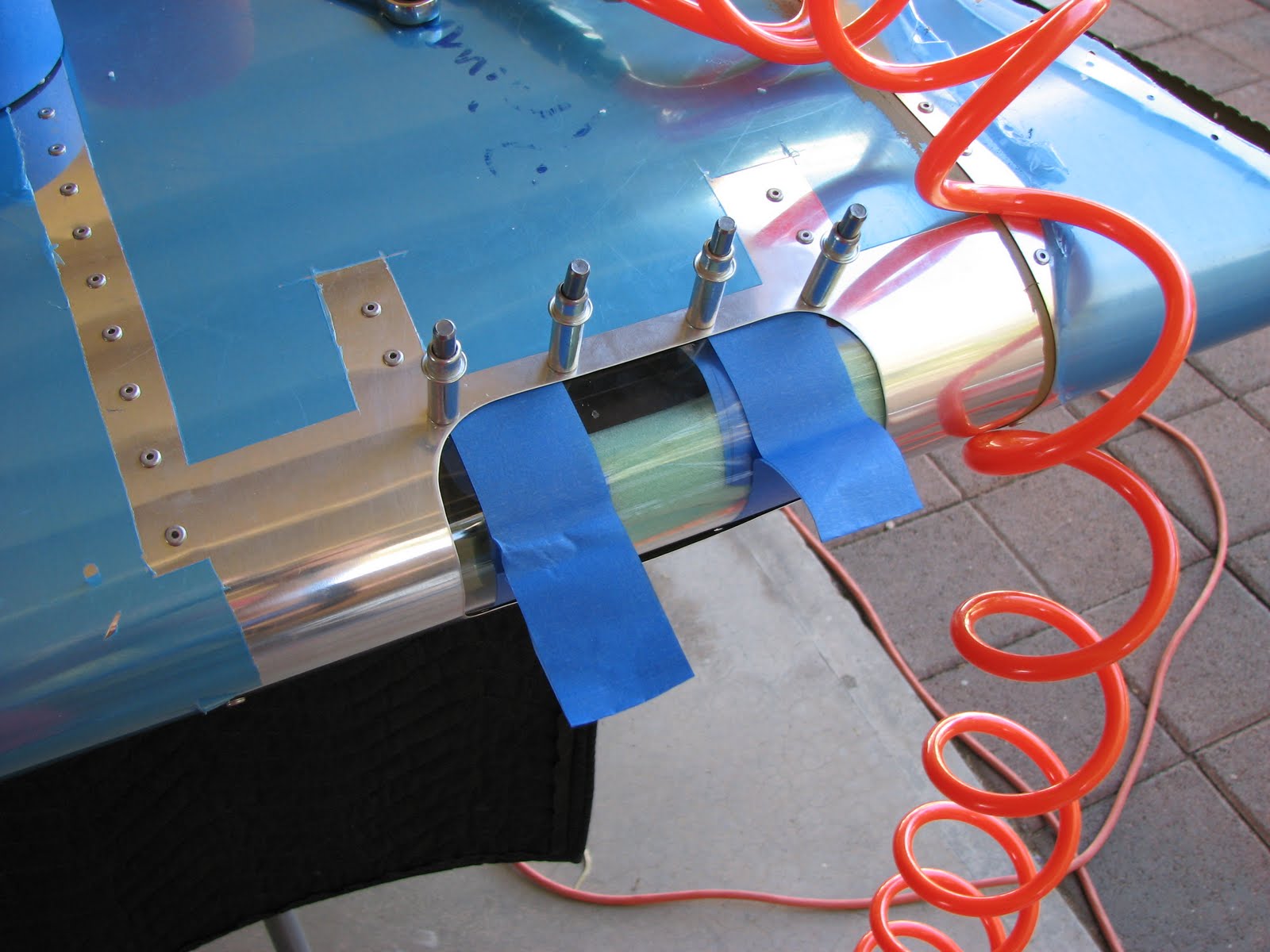
For drilling the lower screw holes I used the same approach although I found it hard to pull while drilling because I would have had to swap my hands, using the weak hand for drilling. I found some foam to stash in between the landing light and the cover to provide some pressure from the inside. Obviously I did this through the open wingtip. The foam held it tightly in place. Then I marked the left and right side of the cutout on the cover for the next trimming process.
By the way, there was no #30 plexiglass drill bit in my Avery tool kit. They provided a #40 and a #27. The latter is required to final drill the holes in the cover. The manual was asking to start drill #30 through the screw holes, probably to match the size of the hole which could help center the drill IF it wasn't a plexiglass drill. A plexiglass drill has a long, sharp tip and so it wouldn't get guidance from the surrounding hole early enough to make a difference I believe. I used the #40 drill to start the holes, taking extra care to center it well. This is how it came out.

Then I used the nutplate brackets to put the final markings on the glass and got started on the final trimming step.

After a lot of cutting and melting (the shop looks like a mess!) and sanding (I wish I had a belt or disc sander!) this is how it came out.

Now it was time to countersink the plexi to match the dimples in the skin that I put in in the same step. The already installed landing light looked like it could interfere with this task but allowed for just enough clearance to get the yoke in there when moved to its rearmost position and using the full travel of the angular axis (full up and down travel).
For countersinking I used the hand tool. It turned out that the deburring bit has the same thread as the countersink bit and so I put it in the crank handle and used a screw head as reference.

Time to rivet the nutplates to the bracket. First I deburred these pieces carefully. I didn't want to leave a little sharp edge pressing on the plexiglass that could cause cracks later.

And here we have the final brackets.

And then I learned that I need double sided tape to hold the brackets in place before the screws do that job. Sometimes I wish Van's would put a note at the beginning of a section stating which stuff you'll need to complete the section that is NOT part of the kit. Now I am waiting for amazon to get the tape to me, which is supposed to be tomorrow.
When I cleaned the markings off the glass I noticed little cracks protruding from two holes on the upper side of the glass. I stop-drilled them with my #40 drill (yeah, that's big for stop-drilling but the smallest size of a plexi drill bit I have). I also noticed then that there were a number of little cracks at the upper and lower edge which I had sanded. I used a soldering iron to melt into them and hopefully stop them. I don't know how I caused this but for now the damage is not too bad as all the fixes I had to do will be covered by the skin and supported by the brackets. I just hope that I caught all these cracks before they grow into the visible area.


No comments:
Post a Comment