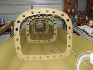
Finishing Section 11 as far as it was reasonable without attaching the control surfaces to the tailcone, I realized I had a storage problem. The tailcone was still using up the better part of my little shop and it was tedious to move around it. With the wing kit arriving in a few weeks I had to find a better place for it for long-term storage.
Fortunately, we have a really long covered patio and so the decision was to find a cozy place for it out there.
On the right side you can see part of the wing cradle I inherited from Tom who just finished his RV-6A and didn't need it anymore.
As with the Stabilator, storing a structure like this outside requires sealing it up so the various Southern Arizonan insect wouldn't find a way inside. I covered up the tail with a left over Harbor Freight coupon flyer.
I think this is more than appropriate as most of the tools i am using to build this RV are indeed provided by HF.
Covering the front was a bit tricky as it's a large area to fill.
I used painter's paper that is used to cover the floor before starting a messy job.
With the structure sitting halfway inside the box the parts came in, I believe it to be roll resistant enough to not get blown over even in a bad storm. This has to last until the front fuselage is done at gets then joined with the aft part.
Oh, BTW, if you were wondering. The length of this tailcone is precisely 9ft.
Sunday, August 29, 2010
Saturday, August 28, 2010
Trim Servo and Arm Assembled
The crimping pliers arrived in time on Friday and they are really a good bargain considering the high quality and comparably low price. So, if you are considering getting some, take a look at SteinAir's pliers before making your choice.
The crimping was real easy and I finished the wiring on the aft tailcone as well as on the trim servo.
The final assembly of the actuator arm for the trim servo didn't reveal any surprises either.
I later found out that I messed up one crimp on the servo that I will have to redo when I order another male spade connector from Van's. I'll probably wait with that until I have something else to order with it as shipping a 40 cents part is ridiculous.
Now I stored these parts away until I get to final assembly.
Thursday, August 26, 2010
Van's is busy!
It appears Van's business is thriving! Since I ordered my fuselage kit and them cashing my advance payment check early August, I hadn't received a confirmation and schedule letter yet. I asked them via email if it got lost or if they hadn't sent it out yet. Barbara took two days to just answer my email telling me that they are behind on these letters and the scheduling as they have so much to do.
I am glad at least they are having an increase in sales! That ensures they will still be there when I need some parts in the future. Bad part is I don't know when the fuselage is going to arrive but by then I should be still busy with my wing kit.
No problem!
BTW: I should get my crimping pliers before the weekend to ensure that I can play around with those connectors and I should be able to test the trim servo then.
Sunday, August 22, 2010
When everything goes wrong ...
Puh, that last session in the shop was quite hard to take. Pretty much everything went wrong.
At first I wanted to continue on the trim servo assembly and crimp the connectors onto the wires. The day before I had stopped by Harbor Freight and grabbed crimping pliers as I have always preferred to solder instead of crimping, so I didn't have any yet.
The tool looked cheap, was cheap and turned out to be completely wasted money. The pliers are so flimsy they didn't even put a dent in the barrel of the connectors. I am now waiting for real pliers to arrive from SteinAir.
Well, with this operation stalled, I moved on to put together the actuator arm for the trim tabs or ASTs. This one worked pretty well until I hit the part were I was supposed to rivet in two AD3-9 rivets. These are pretty long and I hadn't dealt with any rivets that long yet. I thought it was an easy job as I had just purchased this new pneumatic squeezer.
That did not turn out well at all though. The problem was that the squeezer's piston had hardly moved when it already engaged the rivet and at that wide open angle the piston does not develop enough force to compress the rivet.
So I took off the yoke and put it on the manual squeezer. Now, I expected a quick job and - yuk - failed again!
This time the yoke wouldn't open up enough to even get the rivet in between the dies! I had to take out the backstop of the movable arm of the squeezer to trick it to say "Ahhhh" a bit better and get that rivet in between. My anger at that point was quite high and you can tell by the so-so squeezing job I did on them. I think it'll be alright as they are not really structural and only have to hold the threaded insert in the tube.
And finally when pulling the AD42H rivets on the tube brackets, I didn't push hard enough on one of them and the head didn't have full contact with the bracket surface. Argh! ;-) Fortunately, one of my ancestors must have been a smith as I was able to artistically apply the force of a light hammer in a way to convince the rivet head to make a full contact.
Whew! I think none of the sections has given me so much headache so far. I wonder if it's me or just bad luck.
Here's the end result of a few hours of cursing and cussing:
Friday, August 20, 2010
Nutplate Mystery Resolved
I wanted to add photos to the previous entry but when I took them tonight, I noticed I had screwed something up and went ahead to fix it. So I ended up working along a bit further and I'll be adding photos to this entry instead as they somehow belong together.
Remember how I said I spent some time yesterday to verify that a certain nutplate that looked different from the one in the plan is actually correct? Well, I can confirm that Dave's motto: "if doesn't look right, it probably isn't right" has been proven yet again!
Here's the photo of how far I got yesterday. Look at the nut plate closely.
ok, this one shows an almost diamond shaped nutplate. The one in the manual did not look like that but was rather wavy in its shape.
Now look what I found in one of the bags that seem to contain all the hardware for the trim servo.
Aha! Among the nuts I was looking for there's also this nutplate and it happens to look just like the one in the manual. Let's see .... It turns out this one is listed as a K1000-8, exactly the one called out in the manual. Now what did I install then???
A closer look at my sorter showed it was a K1100-8, my brain must have refused to accept this little detail in lieu of another nutplate of similar name. Until now!
So, I started to drill out those rivets, put the right nutplate in place and got to use my new rivet squeezer again! I am getting better at developing a feel for it already.
Looks nice and this time it is correct.
The rest was relatively easy although quite time consuming. Pressing in those plastic bushings and filing them down without filing into the metal was pretty hard and almost impossible to avoid as they are supposed to be almost flush with the surrounding material.
This is how far I got.
What's that cleco doing there?? Well, when I was looking for those nuts, I must have dropped one and they are really tiny? I was looking for it for a while but could not manage to retrieve it. So, it's more stuff to get from Van's. BTW, I can't believe that they really just add the exact amount for parts that have a value of maybe 3 cents. I'd really think they wouldn't run into bankruptcy if they added one of each of these cheap parts above the very necessary amount to avoid having to spend a few bucks on shipping for such a mishap.
UPDATE: I ordered the "missing" nut and some other parts. Once they arrived I found out that the nut was not missing at all. It just turned out that the quality of these little nuts (MS21042-06) is so bad that in my case 2 out of 8 would not go onto the corresponding screw. At least trying to start the nut with my fingers failed in these two cases. Fortunately, I had ordered two replacement nuts - just in case - and it turned out to be just enough as one of the just received nuts wouldn't start either.
25% failure rate on these nuts is not acceptable in my eyes. Particularly because Van's provides only the necessary amount of 6.
Anyway, I'll continue with the other parts and put the nut in when it gets here some time next week.
I just noticed this photo doesn't show the pressed in bushings. Oh well, you'll have to wait until tomorrow then ...
Thursday, August 19, 2010
Trim Servo Cage Coming Together
No photos yet, I'll add them tonight when I get back from work.
I started working on the trim servo cage to avoid or, at least, ease the withdrawal pains that Dave experienced when waiting for the next kit.
As I had done almost all the prep work during previous steps, the cutting, deburring, repeat parts of this job were already done. I even had them primed already, so that was left to do was to rivet the nutplate and the stiffeners on.
The manual called out for a K1000-08 nutplate but it SHOWED a nutplate that did not look at all like the one it called out for. So, I spent some time reading ahead, localizing the screw that was supposed to go into it and verifying that indeed I had the right nutplate which was the K1000-08 the manual had asked for.
Countersinking was a piece of cake, now that I have enough cages to let them sit perfectly adjusted and ready to go whenever I need them.
With the last order at Avery (the clecos, remember?) I couldn't resist to also get a pneumatic rivet squeezer. They had a sale and my hand was just hurting too much still from the job on the rear bulkhead as if I could have ignored those huge savings ;-).
Anyway, this nutplate was the chance to try the squeezer on a piece that would be easy to repair if something went wrong. It worked like a blast! I should have so gotten this tool earlier!! I might have actually enjoyed the work on the rear bulkhead and finished it in a fraction of time. A wonderful tool and it will definitely keep its value. try to find a used one if you don't believe me.
Everything else was business as usual. I used to manual riveter for small places to pull the pop rivets with their manufactured head on the inside of the cage and that ended the night in the shop.
Friday, August 13, 2010
Tail Cone Finished
It took just about an hour to finish the tail cone this morning. As I had already set almost all the rivets to be riveted I could start right away doing what I like most - riveting that is.
I'm almost feeling a bit sorry and empty right now after finishing this milestone. Or is it just the fatigue from raising my arm holding the riveter so high and so often in the last few days ...
To get to this point I spent 67.0 hrs on the tail cone, which adds up to 183.5 hrs invested so far.
The manual riveter for tight places came in quite handy when riveting on the half rib that supports the nose cone of the vertical stab.
and another look into the abyss - this time it looks much more realistic as the top skin is on now.
And one last peculiarity that the plans are not really explicit about. I was worrying when I read the steps and I did not look this up in other blogs ahead of time and finally decided to go ahead and make an educated guess and I just confirmed with Dave's blog that my guess was right.
Please look at the three rivet lines and follow them to the edge of the structure.
The middle one that attaches the J-stiffener to the top skin is indeed riveted all the way to the edge and this is the exception to the no-rivets-seven-inches-from-the-edge rule that applies to all other holes of the tail cone. If you follow the plancs step by step you kind of think that this is what you're supposed to do but they don't explicitly tell you that really mean it.
So, to ease your mind... YES, go ahead and rivet the J-stiffener all the way to the top skin!
And if you didn't - not a problem either, you can always ADD a rivet. Removing one is the part that isn't so enjoyable.
Alright, I'm done with the first kit!
I am not going to attach the control surfaces to the tail cone just yet - at least not permanently as it will be much easier to store the cone with those attached and I still can't afford a hangar around here. I think I'll just find a place on the covered patio in the area where the wings will be stored once finished.
I'll add some silica gel inside the cone and cover it up with paper just like I did with the Stabilator which should allow it to sit there for a while just fine.
Now what am I gonna do???? The wing kit is about 4 weeks out and not much else to do on the cone. Maybe I do attach the empennage and install the trim servo and all the other little things so I wouldn't have to do this later. I can take the surfaces off again and put everything into storage then.
Hm ....
Thursday, August 12, 2010
Top Skin is Coming On
I took the day off and after an early morning flight to check if some changes to the plane (adding a parachute and some plumbing) had left it in an airworthy condition (weekend is coming up and a flight to Bisbee is planned). It turned out to be in good shape and so I returned to the shop and took on the last major task of Section 10, which is to close the cone by putting the top skin on.
I was really enjoying clecoing and the skin was already nicely attached....
....when I noticed something disturbing in the far tail section. Let's see if you can guess what caught my attention:
Aha! Baconing or curling of the skin. This could indicate that the edge hasn't been broken enough to overcome the force of the rivet pulling it up (or the cleco in this case). I put in more clecos in the open holes to see if this would fix it but it turned out that you could still see it. It was OK beyond the 8th hole toward the front but really bad in the aft area.
I decided to not take any chances and took the skin off. Yeah, all the nice clecos had to come out again (not all of them I just did half of it and then had enough room to work) and fortunately I just had ordered another edge breaking tool from Avery that I thought looked more promising than the one I had bought there before (the one that is a pair of modified locking pliers). This is how it looks like:
Really simple and you can progressively increase (or decrease) the amount of roll you want to add to the edge while you're doing it. This is exactly what I needed as I wanted to progressively increase the roll while pulling towards the aft section.
I didn't bother to practice on scrap metal and went straight to it. I really did a very strong roll towards the end as I had seen the skin to not be anywhere near where it was supposed to be.
After clecoing the skin back on the same section looked like this:
and from the rear you can see how much roll I applied there at the aft section:
I like this tool. It's very easy to use and much safer to use without the chance to roll into the skin as the other one. The good news is that this little roller tool is even cheaper than anything I have seen for the job yet. I think it was about 15 bucks and comes with a pair of spare nylon wheels.
In case you want to know where you have to increase the standard roll that I had added to the whole length of the skin on both sides, I have a photo with a little blue L mark right in front of the cleco where I had to apply more edge roll towards the aft section.
Now I was ready to go, so I clecoed the whole skin on and after match drilling, taking off skin, deburring, vacuuming, putting skin back on and realizing that everything fit just fine without further trimming of the skin rest I noticed that I had forgotten to prepare the little shoe that has to get riveted onto the top skin which takes the base of the triangular nose cone that covers the forward attachment point of the vertical stabilizer. The part was done but I hadn't riveted the nut plates on yet. So I did this right away.
half way done.
Now, let's do another attention test. Let's see if you can find the error in the following photo that shows the shoe being ready for installation:
Hm, let's see.... it's not the shoe itself. Look closer at the spot where it's supposed to go.... Aha! It's all shiny! Now what could be wrong with that? Dang! I thought for a moment to not worry about it and violate my primer-at-least-on-all-mating-parts rule but then I quickly realized that I would know and I would always remember (and maybe worry) that I left out this spot.
Oh well, we're not in a hurry, are we? So I took off all the clecos this time and removed the skin and prepped and primed this little spot.
Looks much better and I also primed two more parts that will get used in the final steps that I hadn't done yet.
Now, back on with the skin, cleco everything and set the rivets to get the party started.
Looks, like we're finally good to go (I just really hope I didn't forget to do anything inside as now would be the time...., oh well).
Alright, let's do this!
If you don't believe me, watch the clock on the wall in the background! 45 minutes later half of the rivets were pulled and the engineer got pretty tired - but happy. I decided to call it quits for the day and let the rest of the rivets sit for tomorrow. After all, I had to use my left arm for setting the clecos the last time as the right arm seemed to have gotten much heavier during the afternoon...
Here's a look at the product.
and another one that shows you that I really don't have a lot of room to squeeze around that massive part of the airframe in this little shop. Did I mention that I have no clue where to store the finished piece yet???
I was really enjoying clecoing and the skin was already nicely attached....
....when I noticed something disturbing in the far tail section. Let's see if you can guess what caught my attention:
Aha! Baconing or curling of the skin. This could indicate that the edge hasn't been broken enough to overcome the force of the rivet pulling it up (or the cleco in this case). I put in more clecos in the open holes to see if this would fix it but it turned out that you could still see it. It was OK beyond the 8th hole toward the front but really bad in the aft area.
I decided to not take any chances and took the skin off. Yeah, all the nice clecos had to come out again (not all of them I just did half of it and then had enough room to work) and fortunately I just had ordered another edge breaking tool from Avery that I thought looked more promising than the one I had bought there before (the one that is a pair of modified locking pliers). This is how it looks like:
Really simple and you can progressively increase (or decrease) the amount of roll you want to add to the edge while you're doing it. This is exactly what I needed as I wanted to progressively increase the roll while pulling towards the aft section.
I didn't bother to practice on scrap metal and went straight to it. I really did a very strong roll towards the end as I had seen the skin to not be anywhere near where it was supposed to be.
After clecoing the skin back on the same section looked like this:
and from the rear you can see how much roll I applied there at the aft section:
I like this tool. It's very easy to use and much safer to use without the chance to roll into the skin as the other one. The good news is that this little roller tool is even cheaper than anything I have seen for the job yet. I think it was about 15 bucks and comes with a pair of spare nylon wheels.
In case you want to know where you have to increase the standard roll that I had added to the whole length of the skin on both sides, I have a photo with a little blue L mark right in front of the cleco where I had to apply more edge roll towards the aft section.
Now I was ready to go, so I clecoed the whole skin on and after match drilling, taking off skin, deburring, vacuuming, putting skin back on and realizing that everything fit just fine without further trimming of the skin rest I noticed that I had forgotten to prepare the little shoe that has to get riveted onto the top skin which takes the base of the triangular nose cone that covers the forward attachment point of the vertical stabilizer. The part was done but I hadn't riveted the nut plates on yet. So I did this right away.
half way done.
Now, let's do another attention test. Let's see if you can find the error in the following photo that shows the shoe being ready for installation:
Hm, let's see.... it's not the shoe itself. Look closer at the spot where it's supposed to go.... Aha! It's all shiny! Now what could be wrong with that? Dang! I thought for a moment to not worry about it and violate my primer-at-least-on-all-mating-parts rule but then I quickly realized that I would know and I would always remember (and maybe worry) that I left out this spot.
Oh well, we're not in a hurry, are we? So I took off all the clecos this time and removed the skin and prepped and primed this little spot.
Looks much better and I also primed two more parts that will get used in the final steps that I hadn't done yet.
Now, back on with the skin, cleco everything and set the rivets to get the party started.
Looks, like we're finally good to go (I just really hope I didn't forget to do anything inside as now would be the time...., oh well).
Alright, let's do this!
If you don't believe me, watch the clock on the wall in the background! 45 minutes later half of the rivets were pulled and the engineer got pretty tired - but happy. I decided to call it quits for the day and let the rest of the rivets sit for tomorrow. After all, I had to use my left arm for setting the clecos the last time as the right arm seemed to have gotten much heavier during the afternoon...
Here's a look at the product.
and another one that shows you that I really don't have a lot of room to squeeze around that massive part of the airframe in this little shop. Did I mention that I have no clue where to store the finished piece yet???
Wednesday, August 11, 2010
Left Side Skin Riveted
Another 2 and something hours took care of the left side skin. But first I decided to do something about the trim servo wire that looked like it would be prone to chafing. I put some padding underneath and kept the whole assembly in place by pouring some RTV over it.
I hope this takes care of this problem as going back to this spot would be really hard to do later ...
Not much else to report as the left skin went on - oh, how surprising - just like the right skin. This is how it looked like after two hours of riveting.
I hope this takes care of this problem as going back to this spot would be really hard to do later ...
Not much else to report as the left skin went on - oh, how surprising - just like the right skin. This is how it looked like after two hours of riveting.
Tuesday, August 10, 2010
Right Side Skin Riveted
Fortunately for me, Tom, N811WT - yes the yellow RV-6a that recently had its maiden flight, had some copper clecos he could lend me. As expected the package from Avery didn't arrive yet and as they don't provide tracking number I don't know how far out it is and I was a lame duck without some extra clecos and the tail cone sitting in the shop waiting to get riveted.
So, I started to put those extra clecos in and get the cone ready for action. You can see Tom's clecos as I marked them with masking tape.
After the structure was well supported I put in the right bushing support bracket and match drilled the holes on the J-stiffener side. Again I didn't need the 12" extended drill bit for this but now I could see how someone might have to use it depending on the type and shape of drill they might be using.
Besides the mess this kind of work above a finished structure is creating - metal chips were all over the place - this went fine again and I had no trouble getting it riveted in. BTW, you might want to not use a cleco after drilling the first hole into the bracket as it will sit so close to the next hole to drill you will certainly have a hard time to not interfere with this cleco. This is why they might suggest the extended drill bit. Another way of supporting the bracket is to use a cleco clamp and a piece of wood to raise one clamp above the J-stiffener. This worked much better for me as the force of the clamps is much higher and both brackets had quite some clearance between the J-stiffener and the bracket side I had to drill in. The clamp pulled the bracket side and the J-stiffener close together and this was better than using a cleco. This also made it easier to provide clearance for the drill and therefore making the extended drill bit obsolete.
Inserting the snap bushing was easy and this is how it looked like to a mouse sitting inside the cone - wielding a camera 20 times heavier as itself.
On to the major riveting job it was. With everything prepared and ready to got I started setting the rivets in the open holes on the right side skin realizing that there are a LOT of rivets in the cone and that this might take a while to finish.
I was dead on with this hunch! Two hours after finishing the bracket I pulled the last rivet on the right side skin.
It was just after 9:30 PM at that point and I called it quits for the night.
It looks great though and the structure is already significantly sturdier than with the clecos alone. I'm eager to finish the left side now to see how weight and rigidity will turn out!
Sunday, August 8, 2010
Running Out Of Clecos
I started the day late as I had to drive my beloved wife to the airport at 4 am and all I wanted after getting back home was to continue the rudely interrupted dream I had before.
The day in the shop started a bit before noon and I finished installing the static system which I left early the day before. So, the silicone tubing got installed and sealed/glued to the static ports with RTV (which I had to get at Checker Autoparts before I could start with this job as I didn't have any). Everything went fine with this and installed smoothly.
After tucking in the wires and static line with cable ties, it was on to adding the shoulder skins. I started with the left side and it went on without any hesitation. All the holes lined up just fine and little force was needed to bent it in shape while setting the clecos.
It was about then that I noticed an upcoming problem. Please look at how many clecos are set on the left shoulder skin and notice that the tail hadn't had any yet.
OK. Now follow my eyes as I am about to grab the next cleco to set:
Aha!!! I assume you see the problem. This is what is left for finishing clecoing the left side and doing the complete right side which isn't even on yet.
At this point I realized with a hint of sadness that I wouldn't be able to finish the shoulder skins today. Interestingly I had already ordered 200 additional clecos a few days ago as I was expecting to run short during the upcoming wing assembly. I did definitely not expect to run out during the tail cone.
In case you're wondering about the number of clecos I started with. I bought the Avery toolkit which contains the amount of copper clecos Van's listed on their page describing the required tools for the 12. The number is 350. Now, unless you're willing to allow the skins to not sit tightly on each other before starting riveting (and I am NOT) you will not have enough clecos for this step I am working on right now.
I don't want to be too scientific and determine the exact amount I would have needed but I guess that another 200 is on the safe side and would get this job done with skins perfectly aligned and controlled.
Well, I overcame this little episode of frustration - the ordered clecos probably arrive on Monday or Tuesday - and went on to finish what I could do without attaching the right skin.
This happened to the the installation of the left bushing bracket which will support the control cable for the rudder on the left side. This has to be clecoed match drilled, removed, deburred and put back in place to rivet it to the skin. Here's the result with the snap bushing installed. I actually did not need to use the 12" drill bit that was part of the toolkit in this step, although it is suggested in the manual. Maybe on the right side...
Then it was on to attach the right skin with was left of the clecos. I did remove a few from heavily clecoed areas that seem to have settled a bit since I installed them and therefore didn't need that much support for now.
This was pretty good. On the tail I ran out though. And so I didn't want to install the snap bushing bracket here as it provides a little bit of support for the heavily bent skin and without being clecoed and formed to the aft bulkhead I am afraid to put unnecessary tension on the skin. And it is easy to do once I get the missing clecos.
This left me only to admire the look of the fast forming abyss when looking from the virtual cockpit into the tail cone.
Breathtaking, isn't it? I am now 56 hours into the tail cone assembly.
Saturday, August 7, 2010
Side Skins Clecoed
This was a short day as I was going to the range early in the morning meeting old friends and shooting an IPSC match with them. So I didn't start in the shop before 2 pm.
I clecoed the side skins on and routed the wire for the trim servo along the left skin and installed the thread that will later pull the control cables for the Stabilator through the tail cone.
The I riveted the static ports into the side skins and ran into the same problem as most first time builders.
I had never removed the mandrel from these static port rivets and it was not so easy as the side skins are very wobbly and I didn't want to bend them while banging on the mandrel with a hammer. I followed Dave's advice (as often) and clamped a piece of wood behind the rivet (after drilling a whole in the wood for clearance) and THEN banging on it. While my heart stopped beating with every blow I threw on that poor mandrel, it get the job done and the skin didn't take any harm.
That concluded the building for today and I let the rest sit for the next day which was supposed to be another short shop day - although for different reason than what I thought.
Subscribe to:
Posts (Atom)